Figure 3 motherboard wiring diagram – Detcon 610-N4X User Manual
Page 8
Model 610-N4X
610-N4X Instruction Manual
Rev. 2.2
Page 4 of 8
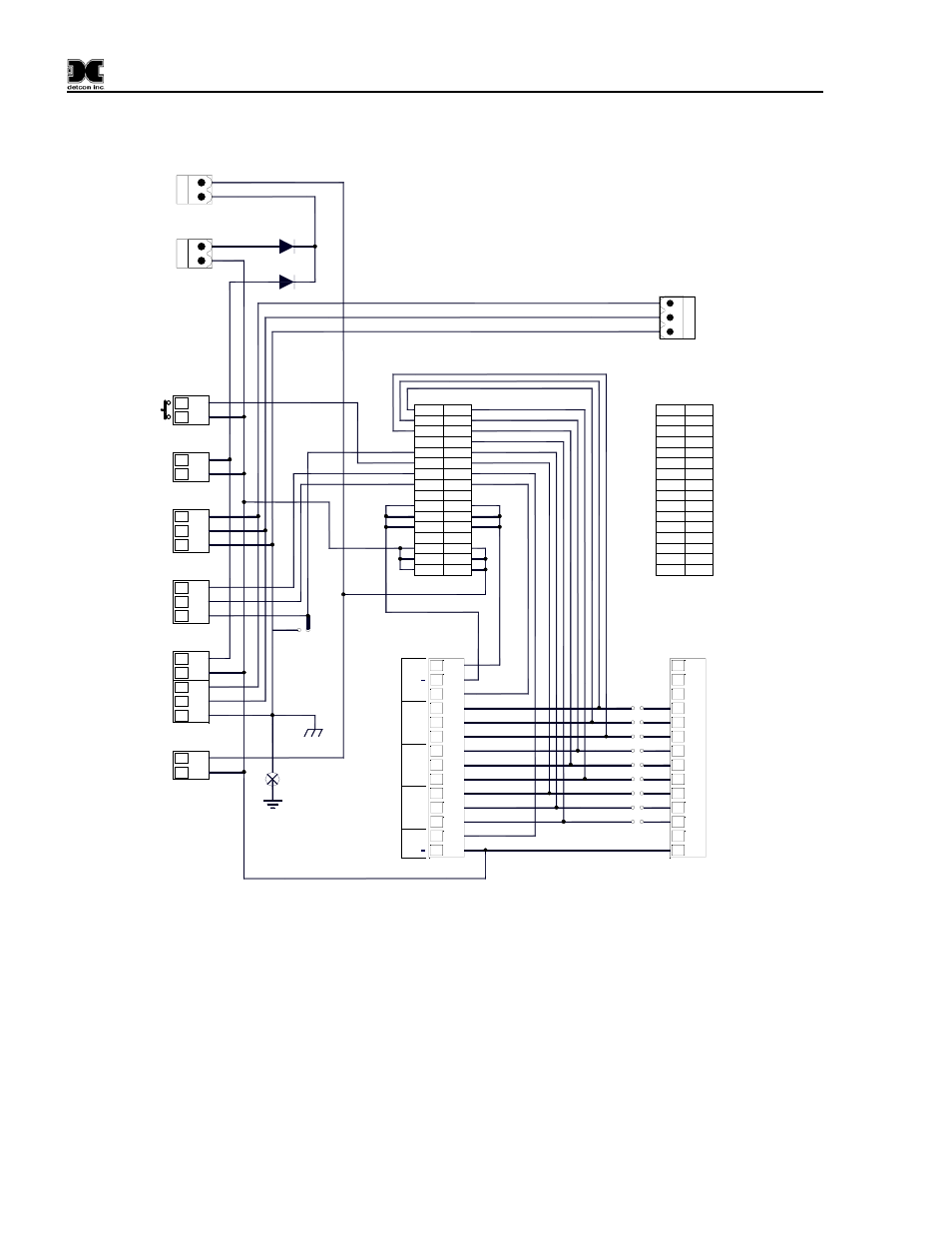
3. If applicable, terminate the discrete 4-20mA outputs to external device(s). Terminals are labeled “4-
A1
C1
C2
A2
A3
C3
C4
A4
A5
C5
A6
C6
C7
A7
A8
C8
C9
A9
A10
C10
A11
C11
C12
A12
A13
C13
C14
A14
A15
C15
A16
C16
A2-COM
A2-NC
A2-NO
FLT-COM
FLT-NC
FLT-NO
4-20 OUT
4-20 IN
--
XM+
XM+
XM+
--
VDC+
VDC+
VDC+
A1-NO
A1-NC
A1-COM
--
485-A
RST
485-S
485-B
--
XM-
XM-
XM-
--
VDC-
VDC-
VDC-
GND
ALM COIL
-
+
RS-485
ALM POWER
L1
N
+
-
N
GND
A(+)
B(-)
Shld
VDC IN
ALM RESET
L1
-
+
VAC IN
P14
P15
P16
P17
P18
P20
PS DC
-
+
P12
BRKR
P11
1
2
1
2
1
2
1
2
1
2
3
1
2
3
1
2
1
2
3
4
5
1
2
3
4
5
6
7
8
9
10
11
12
13
14
P11
1
2
3
4
5
6
7
8
9
10
11
12
13
14
JP1-JP5
A
B
C
D
E
F
G
H
I
P12-P16
mA
NC
+
COM
NC
NO
NO
NC
NO
COM
COM
+
ALM
1
OU
T
4-
2
0
FAULT
S
ENS
O
R
ALM
2
A1
C1
C2
A2
A3
C3
C4
A4
A5
C5
A6
C6
C7
A7
A8
C8
C9
A9
A10
C10
A11
C11
C12
A12
A13
C13
C14
A14
A15
C15
A16
C16
CH1
CH2-CH6
RS-485
Shield
to Gnd
Earth
Ground
Tie to
Chassis
CH1
CH2-CH6
Typical
Jumpers
D2 6A 50V
D1 6A 50V
N
L1
GND
PS VAC
P13
1
2
3
P19
Figure 3 Motherboard Wiring Diagram
4. If applicable, terminate the RS-485 serial output to external device(s). Terminals are labeled “RS-
485” (A+, B–, and Shield, Figure 3). If applicable, terminate RS-485 Shield to Earth Ground via the
jumper tab located to the left of the RS-485 terminals. Place the jumper on the bottom 2 contacts to tie
RS-485 shield to Earth Ground or place the jumper tab on the top two terminals for storage.
5. If applicable a Remote Reset Switch can be utilized by connecting a Momentary, Normally-Open
Switch to P14 (ALM RESET).
6. Earth Ground can be connected to the ground point located in the lower left quadrant of the
motherboard.