4 remote alarm reset, 0 installation, Remote alarm reset – Detcon 610-N4X User Manual
Page 7: Installation, Figure 2 mounting, Detcon inc, Test
Model 610-N4X
610-N4X Instruction Manual
Rev. 2.2
Page 3 of 8
NOTE: If the Battery Option is installed (610-N4X-BBU), the batteries are connected to P15 (VDC IN).
Do not use the DC output of “ALM POWER” (P18-1 and P18-2). The Batteries are not designed to
provide power for alarm devices.
Mounting hardware is provided on the 610-N4X motherboard for two additional Auxiliary Alarm Relay
Boards.
1.4 Remote Alarm Reset
A remote mounted normally open momentary switch may be used to reset the alarms of all Model 10
controllers. “ALM RESET” (P14-1 and P14-2) provides a set of terminals to connect the switch across every
Model 10 Controller (Figure 3). The reset function is effective when the Model 10’s respective alarms have
been programmed in the latching position and alarm conditions have passed. Each Model 10 controller also
has its own discrete alarm reset switch, discussed further in the Model 10 Controller Manual.
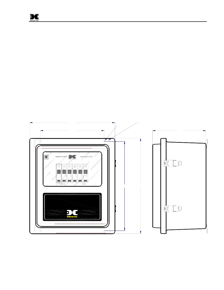
2.0 Installation
1. Securely mount the 610-N4X Enclosure in accordance with Figure 2.
TEST
RESET
ALARM
MODEL 10
FAULT
ALM 1
ALM 2
TEST
RESET
ALARM
MODEL 10
FAULT
ALM 1
ALM 2
RESET
ALARM
MODEL 10
TEST
FAULT
ALM 1
ALM 2
TEST
RESET
ALARM
MODEL 10
FAULT
ALM 1
ALM 2
TEST
MODEL 10
FAULT
ALM 1
ALM 2
RESET
ALARM
TEST
RESET
ALARM
MODEL 10
FAULT
ALM 1
ALM 2
Circuit
Breaker
3 AMP
Detcon Inc.
www.detcon.com
Houston Texas
Gas Detection Control System
www.detcon.com
Houston Texas
Detcon Inc.
16.75"
12"
17.85"
16"
10"
Ø0.3"
Mounting Bracket
Figure 2 Mounting
2. Refer to installation and wiring detail of remote mount sensor assemblies as detailed in the Sensor
Instruction Manual. Terminate field wiring from sensors on the 610-N4X motherboard. Terminals are
labeled “Sensor” (mA, + and –, Figure 3).