0 maintenance & repair, Maintenance & repair, Figure 5 power supply wiring – Detcon 610-N4X User Manual
Page 10
Model 610-N4X
610-N4X Instruction Manual
Rev. 2.2
Page 6 of 8
3.0 Maintenance & Repair
The Detcon Model 610-N4X’s modular design allows for minimum ‘down-time’ during maintenance and/or
repair.
Model 10 Control Modules
A Model 10 control module may be changed by simply loosening its mounting screw and sliding the module
out of its card cage. See the Model 10 Instruction Manual for more information on the Model 10 controllers.
Circuit Breaker/Power Switch
If the 3Amp Circuit Breaker/Power Switch should trip due to a high current or over voltage, the circuit breaker
can be reset by pushing the breaker in (‘ON’). If the breaker trips again, a problem has occurred that will need
to be alleviated before power can be restored.
NOTE: The circuit Breaker/Power Switch does not remove VAC from the Power Supply or the
Motherboard. If power is to be completely removed from the unit, the VAC must be disconnected from
the source.
NOTE: On units with Battery Backup installed (610-N4X-BBU), the Circuit Breaker will remove power
from the Unit, but does not disconnect the Battery circuit from the Motherboard or the Low Voltage
Cutoff Board. The Batteries must be unplugged as well as disconnecting the VAC from the source to
remove power completely from the unit.
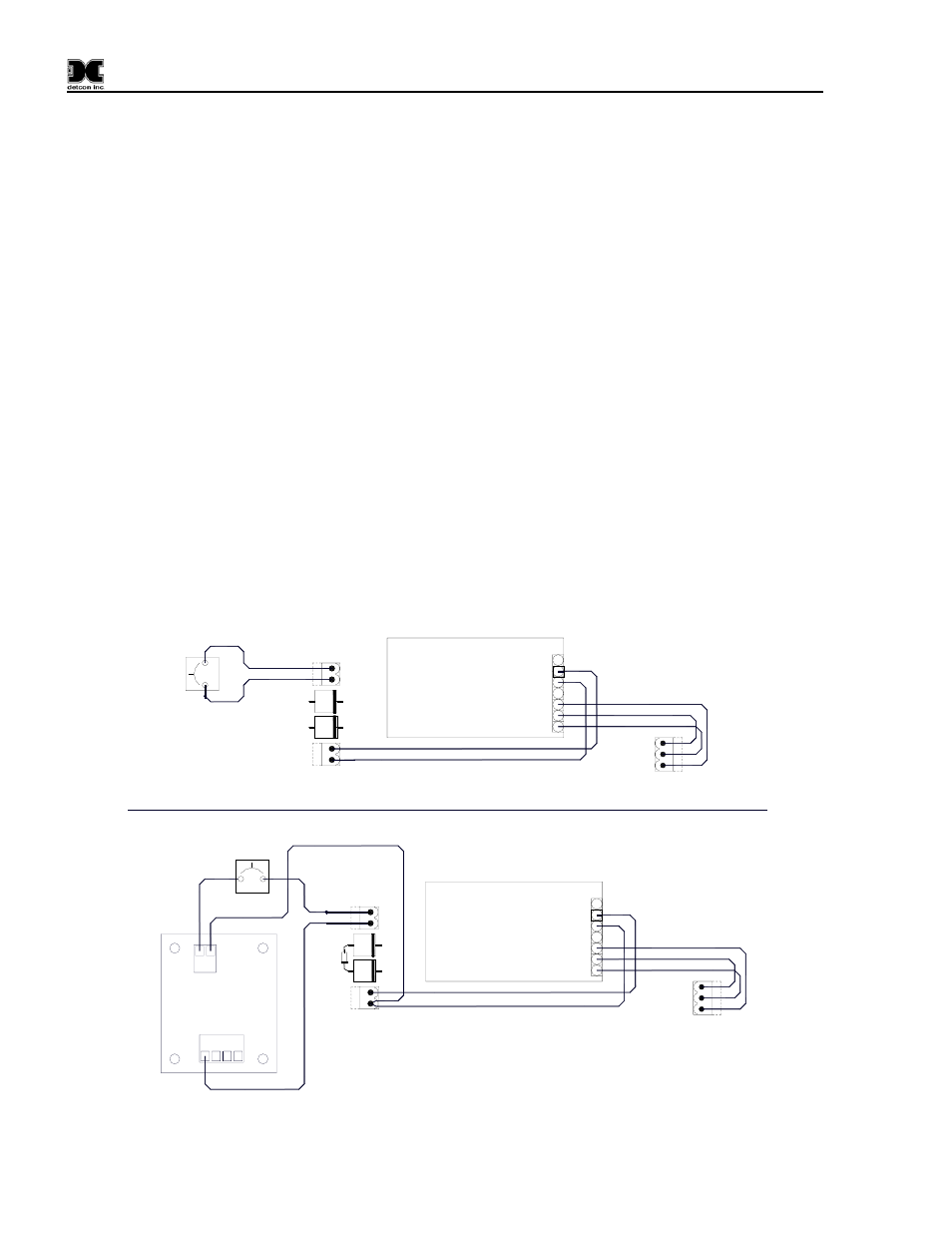
Power Supply Wiring - without Battery Backup
Power Supply Wiring - With Battery Backup
N
GND
L1
PS VAC
P13
PS DC
-
+
P12
BRKR
P11
1
2
1
2
1
2
3
Power Supply
PS
3
2
1
J1
P/N 360-SWS100-024
7
5
GND
L1
N
+
-
Circuit Breaker
RED
RED
RED
GREEN
WHITE
BLACK
BLACK
4
-
6
+
1
2
1 2
P2
Low-Voltage
Cut-off (LV)
P/N 500-505000-000
P1
1 2 3 4
Circuit Breaker
RED
PS DC
-
+
P12
BRKR
P11
1
2
1
2
1N4001
N
GND
L1
PS VAC
P13
1
2
3
Power Supply
PS
3
2
1
J1
P/N 360-SWS100-024
7
5
GND
L1
N
+
-
RED
GREEN
WHITE
BLACK
BLACK
4
-
6
+
BLACK
RED
BLACK
RED
RED
RED
1N4001 diode added
to charge batteries
Note:
Figure 5 Power Supply Wiring