Detcon 1212-N4X User Manual
Page 7
1.6 I
NSTALLATION
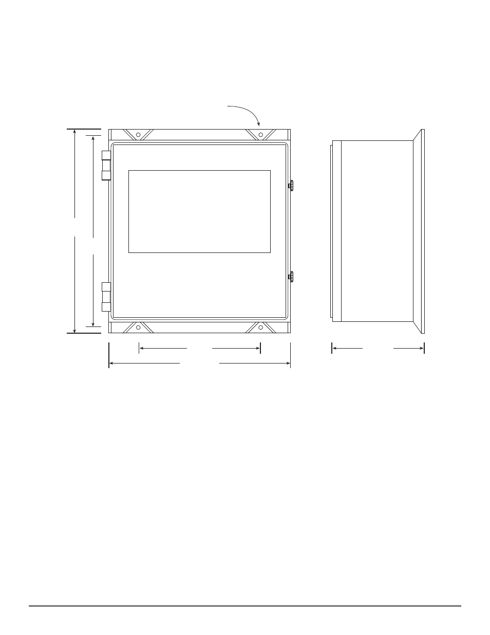
1. Securely mount the 1212-N4X enclosure in accordance with the drawing in f igure 5.
Note: Reference f igure 6 for wiring terminations.
Caution: Observe correct polarity when terminating all input/output field wiring. Failure to do so may result in
circuit damage on power up.
2. Connect 85-264 VAC input to the terminal strip labeled “VAC IN” (L1, N, GND).
3. If applicable, connect a 24VDC source or standby battery to the terminal strip labeled “VDC IN” (+ and –).
4. Refer to installation and wiring detail of remote mount sensor assemblies as detailed in section 3.0. Terminate
f ield wiring from sensors to the 1212-N4X motherboard. Terminals are labeled “Sensor” (mA, + and –).
5. If applicable, terminate the discrete 4-20 mA outputs to external device(s). Terminals are labeled “4-20mA Out”
(+ and –).
6. If applicable, terminate the RS-485 serial output to external device(s). Terminals are labeled “RS-485” (A+, B–,
and Shield). RS-485 outputs may be common or zoned (up to two zones) via the gold-plated jumper tabs.
7. Based on the application and use of relay contact outputs, complete all wiring terminations prior to application
of power. Shut-in controls may be omitted until system test is complete. Terminals are labeled “ALARM 1”
(Com & NO/NC), “ALARM 2” (Com & NO/NC), “ALARM 3” (Com & NO/NC), and “Fault” (Com &
NO/NC). Relay contact outputs may be discrete or zoned via the gold-plated jumper tabs. Relay contact outputs
may be used in conjunction with the multiple alarm relay circuit as described in section 1.3.
Model 1212-N4X NEMA 4 Control Enclosure PG.7
23.07
14
20.63
Mounting Holes - 7/16" Dia.
10.25
21.81
Figure 5