Figure 10 rs-485 id set dip switches – Detcon DM-600IS User Manual
Page 22
DM-600IS
DM-600IS Instruction Manual
Rev 1.5.9
Page 18 of 37
If a jumper tab is installed in the latch position that alarm relay will be in the latching mode. The
latching mode will latch the alarm after alarm conditions have cleared until the alarm reset function is
activated. The non-latching mode (jumper removed) will allow alarms to de-activate automatically
once alarm conditions have cleared.
If a jumper tab is installed in the energize position, that alarm relay will be in the energized mode. The
energized mode will energize or activate the alarm relay when there is no alarm condition and de-
energize or de-activate the alarm relay when there is an alarm condition. The de-energized mode
(jumper removed) will energize or activate the alarm relay during an alarm condition and de-energize
or de-activate the alarm relay when there is no alarm condition.
If a jumper tab is installed in the ascending position that alarm relay will be in the ascending mode.
The ascending mode will cause an alarm to fire when the gas concentration detected is greater than or
equal to the alarm set point. The descending mode (jumper removed) will cause an alarm to fire when
the gas concentration detected is lesser than or equal to the alarm set point. Except in special
applications, toxic gas monitoring will require alarms to fire in “ASCENDING” gas conditions.
Any unused jumper tabs should be stored on the connector board on the terminal strip labeled “Unused
Jumpers” (see Figure 8).
f)
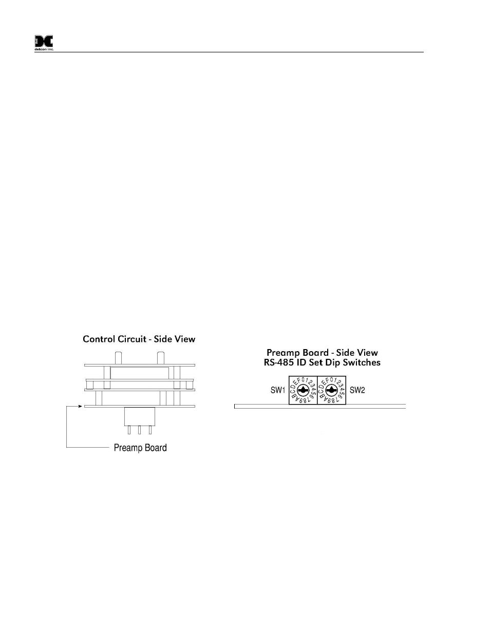
If applicable, set the RS-485 ID number via the two rotary dip switches located on the preamp board
(see Figure 10). There are 256 different ID numbers available which are based on the hexadecimal
numbering system. If RS-485 communications are used, each sensor must have its own unique ID
number. Use a jeweler’s screwdriver to set the rotary dip switches according to the table listed on the
following page. If RS-485 communications are not used, leave the dip switches in the default position
which is zero/zero (0)-(0).
Figure 10 RS-485 ID set Dip Switches
g) Replace the plug-in control circuit and replace the junction box cover.