Installation, Field wiring table (4-20 ma output), 0 installation – Detcon DM-600IS User Manual
Page 17: 1 field wiring table (4-20 ma output)
DM-600IS
DM-600IS Instruction Manual
Rev 1.5.9
Page 13 of 37
DM-500IS-C4H4S
Thiophane
T90 <140
<5% signal loss/year
-20 to +50
-4 to +122
15 to 90
2 years
DM-500IS-C6H5CH3
Toluene
T90 <140
<5% signal loss/year
-20 to +50
-4 to +122
15 to 90
2 years
DM-500IS-C4H6O2
Vinyl Acetate
T90 <140
<5% signal loss/year
-20 to +50
-4 to +122
15 to 90
2 years
DM-500IS-C2H3CL
Vinyl Chloride
T90 <140
<5% signal loss/year
-20 to +50
-4 to +122
15 to 90
2 years
*LELrangeH2isnotCSAapproved.
5.0
INSTALLATION
Optimum performance of ambient air/gas sensor devices is directly relative to proper location and installation
practice.
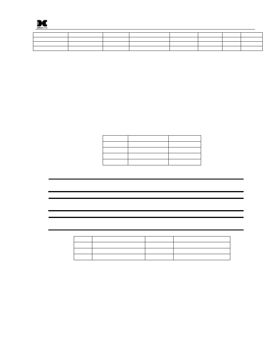
5.1
Field Wiring Table (4-20 mA output)
Detcon Model DM-600IS toxic gas sensor assemblies require three conductor connection between power
supplies and host electronic controllers. Wiring designators are
+
(DC),
–
(DC), and mA (sensor signal).
Maximum single conductor resistance between sensor and controller is 10 ohms. Maximum wire size for
termination in the sensor assembly terminal board is 14 gauge.
AWG
Meters
Feet
20
240
800
18
360
1200
16
600
2000
14
900
3000
Table 3 Field wiring Table
Note1: This wiring table is based on stranded tinned copper wire and is designed to serve as a
reference only.
Note2: Shielded cable may be required in installations where cable trays or conduit runs
include high voltage lines or other sources of induced interference.
Note3: The supply of power must be from an isolating source with over-current protection as
follows:
AWG
Over-current Protection
AWG
Over-current Protection
22
3A
16
10A
20
5A
14
20A
18
7A
12
25A
Table 4 Over-current Protection per AWG
The RS-485 (if applicable) requires 24 gauge, two conductor, shielded, twisted pair cable between sensor and
host PC. Use Belden part number 9841. Two sets of terminals are located on the connector board to facilitate
serial loop wiring from sensor to sensor. Wiring designators are
A &
B
(IN) and
A &
B
(OUT).