Repair and replacement parts, Operating your fan – Triangle Engineering of Arkansas COMFORT AIDE User Manual
Page 3
OpERATINg YOUR FAN
IMpORTANT: dO NOT OpERATE ThE FAN WIThOUT FIRST
OpENINg A WINdOW OR dOOR TO pROvIdE INLET AIR FLOW. IF
FAN IS LOCATEd IN hALL, YOU MUST OpEN dOORS TO hALL TO
ALLOW AIR FLOW INTO ThE FAN.
The air movement in rooms can be increased by closing off parts of
the house. Each room must be treated as a separate ventilating case.
Always open the window farthest from the point that the air will leave
the room.
For best cooling results from your WHOLE HOUSE FAN open only
the windows in the room being use.
IMpORTANT: Fan should always be started on hIgh SpEEd to
prevent possible motor failure.
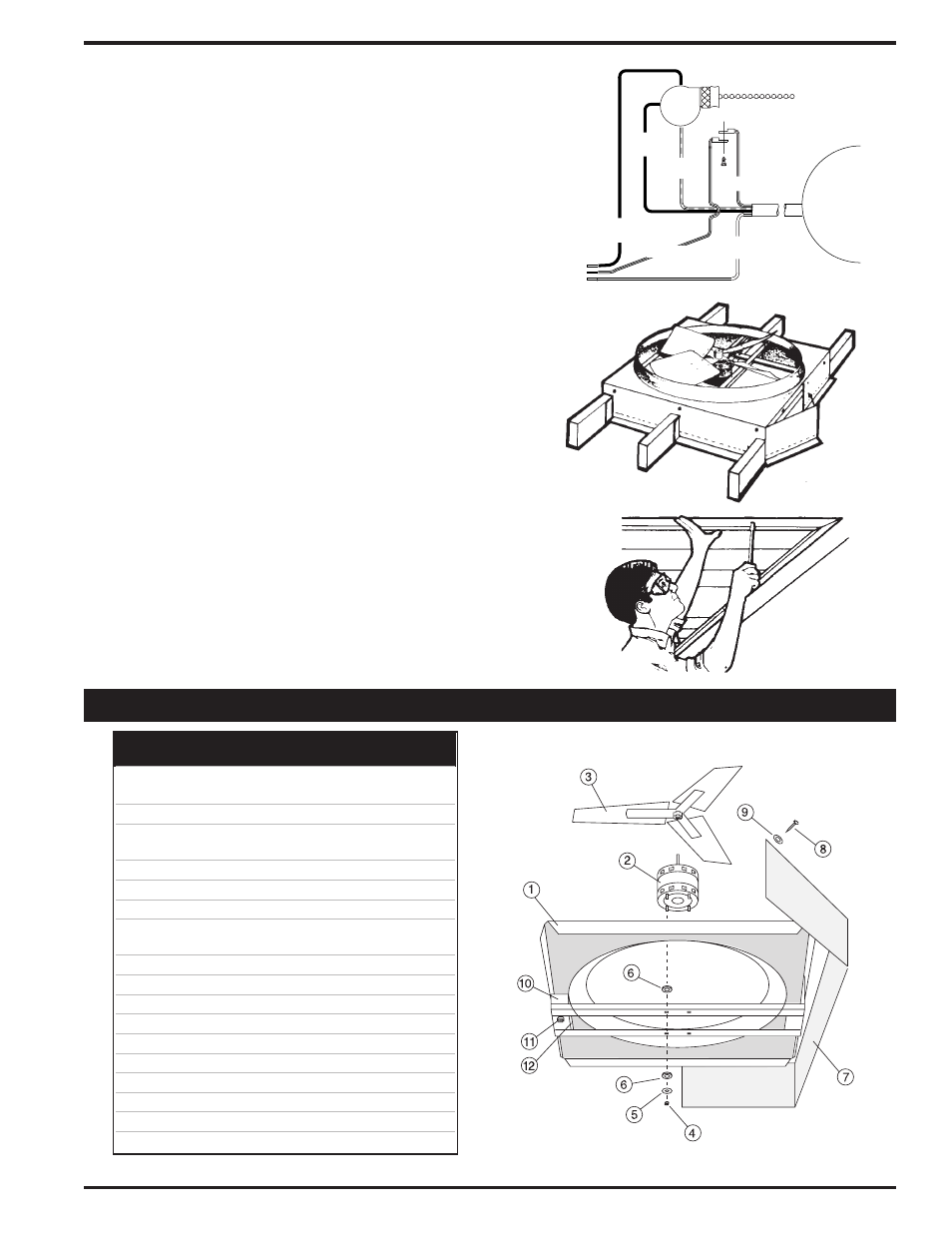
120V
60 Hz
Power
Supply
Motor
BLACK
(high speed)
BLACK
(line)
GREEN
GREEN
RED
(low speed)
WHITE
(common)
FIg. 5
FIg. 6
FIg. 7
Key Part
Part
No. Number
Description
1
WPCA24FRA
24" Fan Frame (Venturi)
WPCA30FRA
30" Fan Frame (Venturi)
2 PP
1
⁄
4
HP Motor
3
WPCA24BA
24" Fan Blade
WPCA30BA
30" Fan Blade
4
PP1032 NUT
Nut (4 req’d - #10 - 32)
5
PP
3
⁄
16
WSH
Washer (4 req’d -
3
⁄
16
Flat)
6
PPRUBMOT
Grommet (8 req’d)
7
PPCA24SKT
24" Fan Skirt
PPCA30SKT
30" Fan Skirt
8
PP10X.75
Screw (12 req’d - #10 x
3
⁄
4
)
9
PPFENDER
Washer (16 req’d -
3
⁄
16
Fender)
10
PPHANDYC
Cover, Switch Box
11
PPPULLSW
Switch, 2-Speed
12
PPSTRAIN
Strain Relief
†
FGCSS24
Shutter - 24" Fan
†
FGCSS30
Shutter - 30" Fan
†* FG2SPWALL
2-Speed Wall Switch
†* FG12HRTIM
12-Hour Timer
†* FG2SP12HR
2-Speed, 12 hr. Timer Wall Switch
† Not Illustrated †* Optional
Specifications subject to change without notice.
REPAIR AND REPLACEMENT PARTS
STEp 4.
- TURN OFF pOWER AT FUSE bOX OR CIRCUIT
bREAkER.
The fan requires a 120 volt A.C. power source with
at least 5 amp capacity. All electrical work must be in accordance
with local building codes using approved material. Follow wiring
diagram as shown below in FIg. 5 to finish electrical installa-
tion. Before restoring power, be certain the fan blades are clear
as the pull chain switch may be in the “on” position. If you are
using a separately purchased wall mounted control, follow
the instructions furnished with that control.
STEp 5.
Cut out the plenum at premarked openings to fit your
ceiling joists. Attach the plenum to the deck using the #10 screws
and fender washers provided . Staple or tack the plenum to the
ceiling joist. Improper installation of the plenum can result in poor
fan performance or possible motor failure. Re-install insulation to
the edge of the plenum. Cover any opening with duct tape. The
plenum must be tightly sealed to the fan, joists and ceiling so the
fan draws air from the living area only. (FIg. 6)
STEp 6.
Install flush mounted ceiling shutter into the ceiling
opening using the #10
1
⁄
4
" screws included in the shutter carton.
Caution should be taken not to effect the free operating action
of the shutter. Drop the pull chain through the hole provided in
the shutter and trim it to desired length. Your installation is now
complete. (FIg. 7)
Page 3