Installation instructions, Tools required for installation, Other materials required fan specifications – Triangle Engineering of Arkansas COMFORT AIDE User Manual
Page 2
Page 2
TRIANgLE’S COMFORT AIdE
fans are easy to install
using ordinary hand tools. It is not necessary to cut any ceil-
ing joists or build any wood frames. The motor and two-speed
switch are pre-wired at the factory so all you have to do is
hook it to a 120 volt AC power source with 5 amp capacity.
Follow these easy step-by-step instructions and you will have
a professional installation.
LOCATION OF FAN
- The most logical place to locate your
WHOLE HOUSE FAN is near the central part of the house.
NOTE - if hall area is chosen, it must have a minimum 32"
width for the 24" fan; 35" width minimum for the 30" fan. Check
attic area to be certain there is adequate clearance above the
fan. Minimum space should equal blade diameter. Inspect the
area where the fan is to be installed. The area must be free of
electrical wiring and pipes.
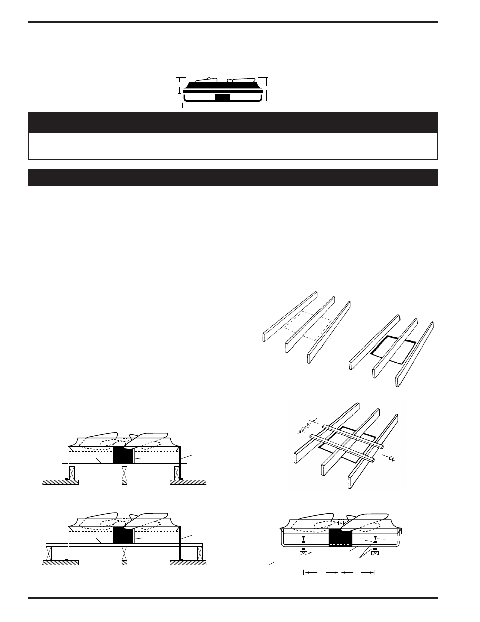
STEp 1.
After installation site has been selected for the fan,
remove insulation from area and select a ceiling joist or roof
truss to be the center line of the fan. Use the shutter carton to
make a template.
*
Use the dimensions listed for your shutter
as shown on the carton. (FIg. 1) Repeat this procedure on the
other side of the middle joist. Drill small holes at each corner
of the area marked on the ceiling. CAUTION: The shutter hole
must equal the “fits hole” dimensions that appears on the shut-
ter carton. Double check fan location from inside living area
before cutting shutter hole.
STEp 2.
If the layout is satisfactory, cut and remove ceiling
material. (FIg. 2) Lift fan into the attic through the hole you
TOOLS REQUIREd FOR INSTALLATION
• Hammer
• Razor blade or
sheet rock saw
• Power or hand saw
• Pencil
• Straight edge
• Measuring tape
• Screwdriver
• Electric drill
• Safety goggles
OThER MATERIALS REQUIREd
FAN SpECIFICATIONS:
B
C
A
CFM
BLADE DIMENSIONS RPM
WATTS
MODEL
H.P.
HI LO
DIAMETER A B C
HI LO
HI LO
VENTILATES
COMFORT COOLS
CA 2421 1/4 4700 3500
24"
30" x 4" x 9" 810 625
450 380 1500 - 2350 Sq. Ft.
600 - 1200 Sq. Ft.
CA 3021 1/4
6000 450
30"
34" x 4" x 9" 795 610
480 410 2250 - 3000 Sq. Ft.
750 - 1500 Sq. Ft.
• 10 Ft. of 1" x 2" wood strips
• 6 Nails (#4 or #6)
• Automatic Ceiling Shutter
• Code required electrical materials
• Duct tape
PLENUM
1" x 2"
ANGLE
PLENUM
1" x 2"
ANGLE
Typical appearance of 24" fan mounted on
ceiling joist 16" and 24" on center and of a
30" fan mounted on ceiling joist 24" on center.
Typical appearance of 30" fan mounted on
ceiling joist 16" on center.
FIg. 1
FIg. 2
*CSS24 Template Size 10
1
⁄
4
x 30
1
⁄
4
CSS30 Template Size 14
1
⁄
4
x 34
1
⁄
4
FIg. 3
Motor
#12 Lag Screw
Rubber Isolation Mounts
Joist
Washer
1" x 2"
6"
Angle
6"
FIg. 4
INSTALLATION INSTRUCTIONS
have just cut. Be careful not to damage the edges of the ceil-
ing when lifting the fan into the attic. IMpORTANT: ThIS FAN
IS dESIgNEd FOR hORIzONTAL INSTALLATION ONLY
FOR vERTICAL AIR FLOW. dO NOT MOUNT IT AT ANY
OThER ANgLE.
STEp 3.
Cut two 1" x 2” wood strips to span three joists.
Locate the 1” x 2” strips as shown in Fig. 3 and nail them
to each joist. Fasten the fan to the strips as illustrated using
the #12 lag screws, washers and rubber isolation mounts.
(FIg. 4.)