D 5216 spray control front, Rear view of spray control – SnowEx VSS-3000 User Manual
Page 38
© Trynex International 2010 L1506
1 — 38
Model # VSS-2000 / 3000
Wiring Instructions and Electrical System
VSS-2000 / 3000 Electrical System
Step 1: Attach vehicle harness rubber plug end to rear of vehicle using supplied hardware.
Step 2: Route harness along vehicle frame and away from any heat sources. Ty-wrap harness to vehicle frame as you go along.
Key Part No.
Description
Qty.
D 5216
Control 1
Sprayer Harness 1
D 5219
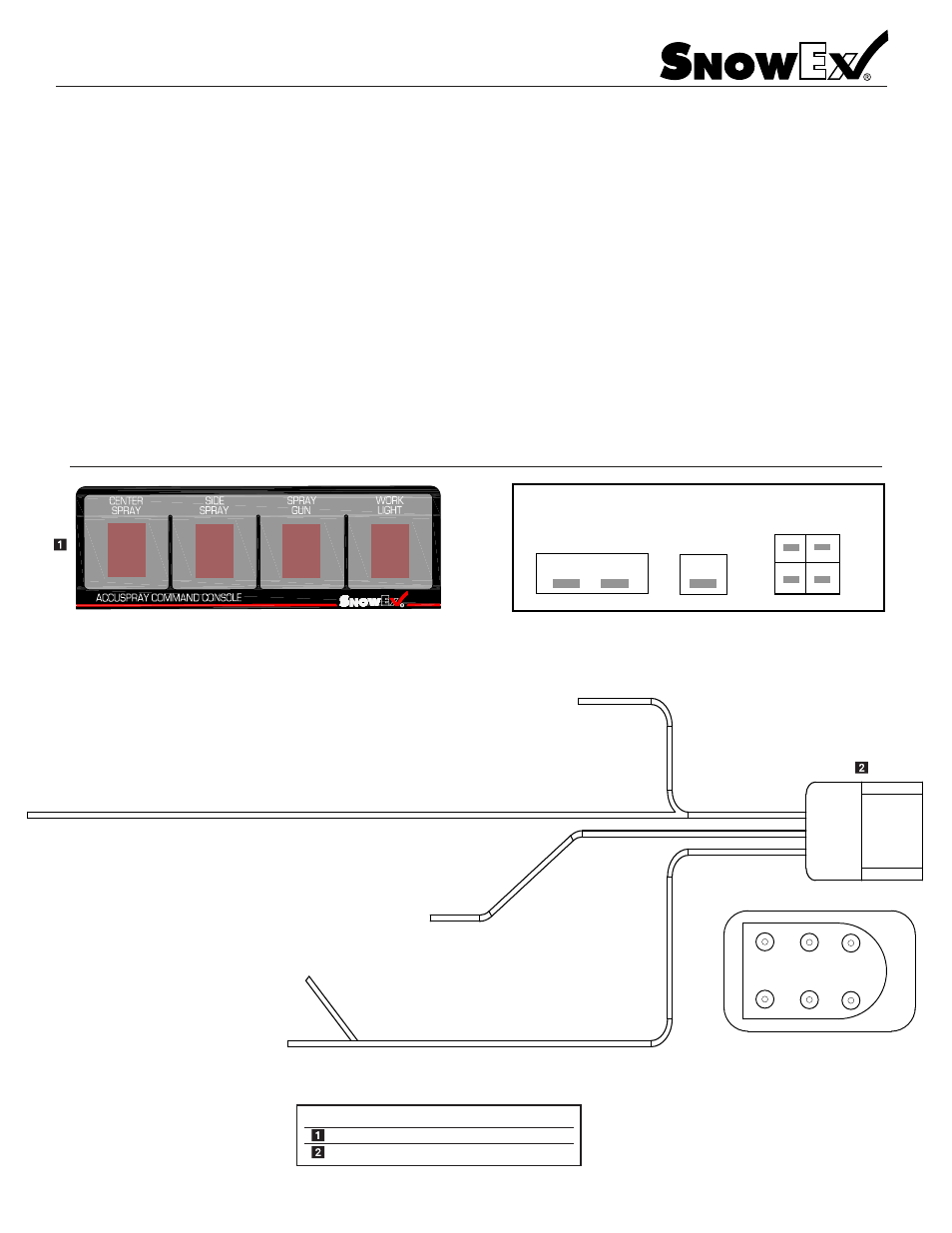
D 5216 Spray Control Front
WHITE
BLACK
YELLOW
RED
GREEN
BLUE
BLACK - Common Ground
BLACK/RED - Work Light
BLACK/BLUE - Center Pump Spray Nozzles
BLACK/YELLOW - Curb Pump Spray Nozzles
BLACK/GREEN - Hose Reel Pump
BLACK/WHITE - CHMSL (brake light)
Plastic (2) Conductor Connector
Plastic (2) Conductor Connector
Plastic (2) Conductor Connector
SAE (2) Conductor Connector
Plastic (2) Conductor Connector
Rear View Of Spray Control
Main Power In
Common
Ground
BLU
GRN
ORG
YEL
Output To
Sprayer
NOTE: Colors Are For Harness Ends
Route (4) conductor block and common ground through vehicle bulkhead using service accesses. If you need to dill a hole
make sure to inspect the area inside and out before doing so, this will minimize any damage to wires or other vehicle
components.
Step 3: Route control power cable through vehicle bulhead to the batter. Connect terminal ends to battery and tywrap
harness to along the way back to the vehicle bulkhead.
Step 4: Select a suitable mounting spot for sprayer control and install with supplied hardware. Once you have the control
mounted, install harness connectors into the back of the control. Leave some slack in harness so the connector are not
under any strain. Ty-wrap all harnesses to proper points, take up any extra harness length and coil up inside the engine
compartment. DO NOT MODIFY HARNESS LENGTH OR CONNECTORS. Connect sprayer harness to bumper plug, then
test each funtion on the control by switching each function on and off to verify proper installation.