Vehicle harness wiring instructions, Work light wiring instructions, Model # sp-2200 – SnowEx SP-2200 User Manual
Page 18
© Trynex International 2010
1 — 18
Vehicle Harness Wiring Instructions
p Take harness assembly and route from the rear of the vehicle to the front. Route harness along frame and attach to
frame holes and frame supports. It is not recommended to attach to fuel or brake lines for obvious reasons. Do not route close
to exhaust system or engine, even though Snowex uses high temperature wiring. It still could melt under extreme heat and short the
Model # SP-2200
spreader electrical system as well as the vehicle electrical system.
2 Mount rear plug above hitch plate using supplied bolts, locate between hinges
or an ).
Make sure wiring and
plug are clear of dump body pinch points. Apply a small amount of dielectric grease to contacts.
p Secure harness from the rear to the front using heavy duty ty-wraps or frame clips along the frame and lighter duty
ty-wraps everywhere else.
S p Drill a 1-1/4 hole in the firewall or use existing access hole c
k
y
cl
o
o h d
d
. Route connector and harness through hole. The power harness from control box to battery will need to be routed
do not connect power at this time.
5: Connect harness to the back of the controller and mount to a suitable location. NOTE: You may want to contact customer
before mounting controller as some prefer not to have holes drilled into the dashboard. Ty-wrap loose controller harness and move
to the engine compartment. Do not mount close to any heater vents.
S p Connect power leads to the battery: Red + Positive, Black – Negative, always connect to the primary battery if using a dual battery
system, secure loose loom to any other large or medium vehicle harness with medium duty ty-wraps; this will secure wiring harness.
p 7 Push the ON/OFF button on the controller to check for power, when that has been confirmed turn power OFF. The electrical portion
of the installation is complete.
from the inside of the cab to the battery – this results from the large amperage connector. Route leads with lugs to battery,
Work Light Wiring Instructions
p Take light kit harness and route from the rear of the vehicle (left side) to the front. Follow main spreader wire route into
vehicle cab and locate next to control mounting position.
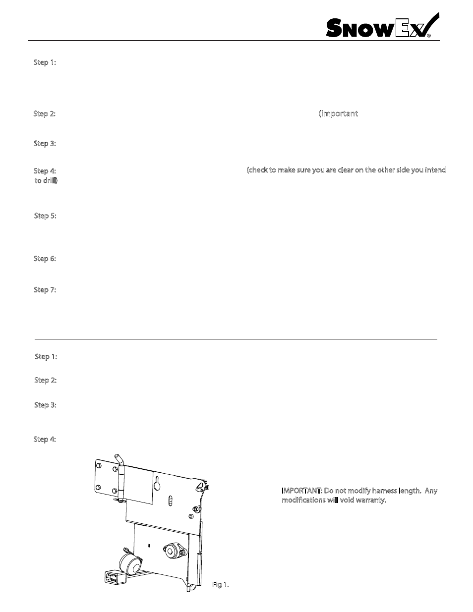
S p 2 Mount rear power plug next to main spreader power plug. Install work light onto spreader (see fig. 1 below) and also connect
harness adapter to light assembly. Do not connect light adapter to main vehicle harness at this point.
e 3 Attach Vehicle harness (pos +) lead to supplied switch. Next attach (pos +) lead coming off main control input power
input power lead. Both the (pos +) and (neg -) connection points will be male/female insulated spade terminals.
lead to switch. The final connection will be to connect the (neg-) wire from the vehicle harness to the main control
S p Connect work light adapter to vehicle plug, test work light by switching toggle on/off.
M O A
o o o f
l
A
d fic o w ll vo