Pilot valve, Pilot valve actuator, Air exhaust – SANDPIPER PB2-A User Manual
Page 3: Between uses, Check valve servicing, Diaphragm servicing
520-130-000
2/97
Model PB1½-A & PB2-A
Page 3
Fig. 6
Gaskets / o-rings
Fig. 9
Sleeve & spool exposed.
Fig. 8
Gasket, item 63, used only on polypro-
pylene models.
Fig. 7
Gaskets / o-rings
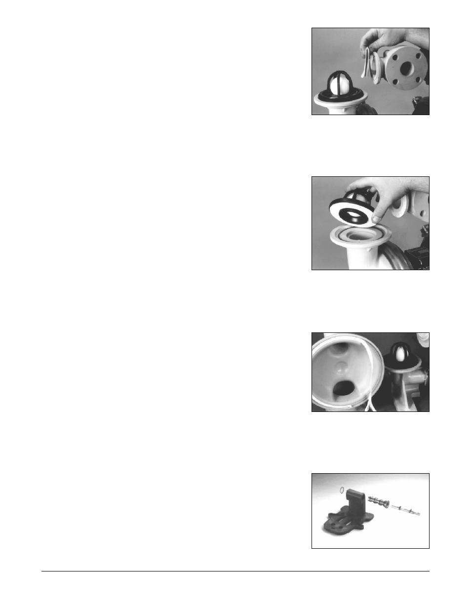
PILOT VALVE
The pilot valve assembly is accessed by removing the main air distribution valve
body from the pump and lifting the pilot valve body out of the intermediate housing
(See Fig. 10).
Most problems with the pilot valve can be corrected by replacing the o-rings.
Always grease the spool prior to inserting it into the sleeve. If the sleeve is removed
from the body, reinsertion must be at the chamfered side. Grease the o-rings to slide
the sleeve into the valve body. Securely insert the retaining ring around the sleeve.
When reinserting the pilot valve, push both plungers (located inside the intermediate
bracket) out of the path of the pilot valve spool ends to avoid damage.
PILOT VALVE ACTUATOR
Bushings for the pilot valve actuators are held in the inner chambers behind the
diaphragms. The plunger may be removed for inspection or replacement. First
remove the air distribution valve body and the pilot valve body from the pump. The
plungers can be located by looking into the intermediate. It may be necessary to use
a fine piece of wire to pull them out. The bushing can be turned out through the inner
chamber by removing the outer chamber assembly. Replace the bushings if pins have
bent.
AIR EXHAUST
If a diaphragm fails, the pumped liquid or fumes can enter the air end of the pump,
and be exhausted into the atmosphere. When pumping hazardous or toxic materials,
pipe the exhaust to an appropriate area for safe disposition (see Fig. 2).
This pump can be submerged if materials of construction are compatible with the
liquid. The air exhaust must be piped above the liquid level. Piping used for the air
exhaust must not be smaller than 1" (2.54 cm). Reducing the pipe size will restrict air
flow and reduce pump performance .When the product source is at a higher level than
the pump (flooded suction), pipe the exhaust higher than the product source to
prevent siphoning spills.
Freezing or icing of the air exhaust can occur under certain temperature and
humidity conditions. Use of a Warren Rupp Air Dryer unit should eliminate most icing
problems.
BETWEEN USES
When used for materials that tend to settle out or transform to solid form, the pump
should be completely flushed after each use, to prevent damage. Product remaining
in the pump between uses could dry out or settle out. This could cause problems with
valves and diaphragms at re-start. In freezing temperatures, the pump must be
drained between uses in all cases.
CHECK VALVE SERVICING
Need for inspection or service is usually indicated by poor priming, unstable
cycling, reduced performance or the pump’s cycling but not pumping.
Remove the four V-Band clamps securing the manifold assemblies to the outer
chambers. Inspect the surfaces of both check valve and seat for wear or damage that
could prevent proper sealing. If pump is to prime properly, valves must seat air tight
(see Fig. 3).
DIAPHRAGM SERVICING
Remove the four V-Band clamps securing the manifold assemblies to the outer
chambers. Remove the two V-Band clamps securing the outer chambers to the inner
chambers. Remove the diaphragm assembly (outer plate, diaphragm, inner plate) by
turning the assembly counterclockwise using a 1
3
/
8
" (3.492 cm) wrench on the outer
plate lugs. For the PB2, use a 1½" (3.8 cm) wrench. To disassemble the diaphragm
assemblies, lock the inner plate in a soft jaws vice and turn the outer plate
counterclockwise from the inner plate using the same wrench. Be sure inner plate is
free of burrs. The interior components consisting of shaft seals, sleeve bearings and
bearing retainers are now accessible for service.