Air inlet & priming, Caution – SANDPIPER PB2-A User Manual
Page 2
Model PB1½-A & PB2-A
Page 2
520-130-000
2/97
AIR INLET & PRIMING
For start-up, open an air valve approximately
1
/
2
to
3
/
4
turn. After the unit primes,
an air valve can be opened to increase flow as desired. If opening the valve increases
cycling rate, but does not increase flow rate, cavitation has occurred, and the valve
should be closed slightly.
For the most efficient use of compressed air and the longest diaphragm life, throttle
the air inlet to the lowest cycling rate that does not reduce flow.
A NOTE ABOUT AIR VALVE LUBRICATION
The SandPiper pump’s pilot valve and main air valve assemblies are designed to
operate WITHOUT lubrication. This is the preferred mode of operation. There may be
instances of personal preference, or poor quality air supplies when lubrication of the
compressed air supply is required. The pump air system will operate with properly
lubricated compressed air supplies. Proper lubrication of the compressed air supply
would entail the use of an air line lubricator (available from Warren Rupp) set to deliver
one drop of 10 wt., non-detergent oil for every 20 SCFM of air the pump consumed
at its point of operation. Consult the pump’s published Performance Curve to
determine this.
It is important to remember to inspect the sleeve and spool set routinely. It should
move back and forth freely. This is most important when the air supply is lubricated.
If a lubricator is used, oil accumulation will, over time, collect any debris from the
compressed air. This can prevent the pump from operating properly.
Water in the compressed air supply can create problems such as icing or freezing
of the exhaust air causing the pump to cycle erratically, or stop operating. This can
be addressed by using a point of use air dryer (available from Warren Rupp) to
supplement a plant’s air drying equipment. This device will remove excess water from
the compressed air supply and alleviate the icing or freezing problem.
MODELS WITH 1" SUCTION/DISCHARGE
OR LARGER, AND NON-METAL CENTER SECTIONS
The main air valve sleeve and spool set is located in the valve body mounted on
the pump with four hex head capscrews. The valve body assembly is removed from
the pump by removing these four hex head capscrews.
With the valve body assembly off the pump, access to the sleeve and spool set
is made by removing a retaining ring (each end) securing the end cap on the valve
body assembly. With the end caps removed, slide the spool back and forth in the
sleeve. The spool is closely sizes to the sleeve and must move freely to allow for
proper pump operation. An accumulation of oil, dirt or other contaminants from the
pump’s air supply, or from a failed diaphragm, may prevent the spool from moving
freely. This can cause the spool to stick in a position that prevents the pump from
operating. If this is the case, the sleeve and spool set should be removed from the
valve body for cleaning and further inspection.
Remove the spool from the sleeve. Using an arbor press or bench vise (with an
improvised mandrel), press the sleeve from the valve body. Take care not to damage
the sleeve. At this point, inspect the o-rings on the sleeve for nicks, tears or abrasions.
Damage of this sort could happen during assembly or servicing. A sheared or cut o-
ring can allow the pump’s compressed air supply to leak or bypass within the air valve
assembly, causing the pump to leak compressed air from the pump air exhaust or not
cycle properly. This is most noticeable at pump dead head or high discharge pressure
conditions. Replace any of these o-rings as required or set up a routine, preventive
maintenance schedule to do so on a regular basis. This practice should include
cleaning the spool and sleeve components with a safety solvent or equivalent,
inspecting for signs of wear or damage, and replacing worn components.
To re-install the sleeve and spool set, lightly lubricate the o-rings on the sleeve with
an o-ring assembly lubricant or lightweight oil such as 10 wt. air line lubricant). Re-
install one end cap, and retaining ring on the valve body. Using the arbor press or
bench vise that was used in disassembly, carefully press the sleeve back into the valve
body, without shearing the o-rings. Re-install the spool, opposite end cap and
retaining ring on the valve body. After inspecting and cleaning the gasket surfaces on
the valve body and intermediate, reinstall the valve body on the pump using new
gaskets. Tighten the four hex head capscrews evenly and in an alternating cross
pattern, at 150 in./lbs. (16.94 Newton meters).
CAUTION
Hydrofluoric acid above 40% concen-
trate should not be pumped with the
polypropylene unit. Check chemical
compatibility chart for other fluids.
CAUTION
Operating temperature limitations are
as follows:
PVDF:
PVDF:
PVDF:
PVDF:
PVDF: 200°F (93.3°C) Max. to 10°F (-12.2°C) Min.
Polypro.:
Polypro.:
Polypro.:
Polypro.:
Polypro.: 150°F (65°C) Max. to 40°F (4.4°C) Min.
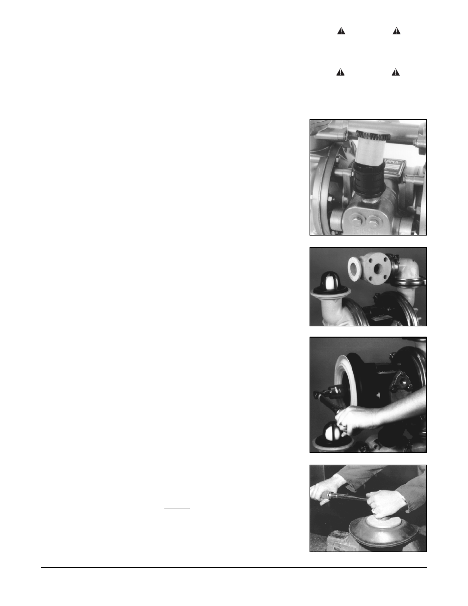
Fig. 5
Torque of diaphragms
Fig. 3
Check balls exposed
Fig. 4
Torquing the diaphragm plate
Fig. 2
Exhaust muffler