Ruppguard, Option for virgin ptfe equipped pumps drawing – SANDPIPER S20 Non-Metallic User Manual
Page 16
520-202-000
9/03
Model S20 Non-Metallic Design Level 2 Page 14
33
45
14
6
16
30
18
19
53
51
47
29
48
17
40
26
26
40
46
40
51
53
51
50
52
56
58
54
57
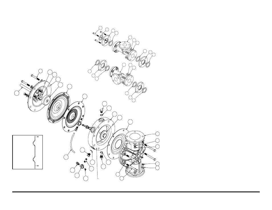
RuppGUARD
™
Option for
Virgin PTFE Equipped
Pumps Drawing
S20 Spill Prevention Repair Parts List
for Virgin PTFE Equipped Pumps
ITEM PART NUMBER DESCRIPTION
QTY
1
031-146-000
Air Valve Assembly
1
(replaces 031-140-000)
031-147-000
Air Valve Assembly
1
(replaces 031-141-000)
45
170-092-115
Capscrew, Hex HD 1/2-13 x 4.00
8
(replaces 170-068-115)
170-092-308
Capscrew, Hex HD 1/2-13 x 4.00
8
(replaces170-068-115)
46
170-108-115
Capscrew, Hex HD 1/2-13 x 5.50
8
(replaces 170-095-115)
170-108-308
Capscrew, Hex HD 1/2-13 x 5.50
8
(replaces 170-095-115)
47
196-149-520*
Chamber, Spill Prevention
2
196-149-552*
Chamber, Spill Prevention
2
48
286-076-600
Diaphragm, Pumping
2
49
518-134-520
Manifold
2
(replaces 518-132-520)
518-134-520E
Manifold, 50mm DIN
2
518-134-552
Manifold
2
(replaces 518-130-552)
518-134-552E
Manifold, 50mm DIN
2
50
538-022-110
Nipple, Pipe
4
538-022-308
Nipple, Pipe
4
51
560-078-611
O-Ring
8
52
618-003-110
Plug, Pipe
4
618-003-308
Plug, Pipe
4
53
618-025-110
Plug, Boss
4
618-025-308
Plug, Boss
4
54
618-031-110
Plug, Boss
4
618-031-308
Plug, Boss
4
55
770-057-600
Spacer, Manifold
4
770-057-552
Spacer, Manifold
4
56
835-005-110
Tee, Pipe
4
835-005-308
Tee, Pipe
4
57
860-055-606
Tube, Sight
2
58
866-060-110
Connector, Tube
4
59
170-111-115
Capscrew, Hex HD 5/8-11 x 3.25
16
(replaces 170-110-115)
Note:
All of
the diaphragms
are to be
installed with
the concave
side facing
toward the
outer
chambers.
59
36
55
36
49
27
41
36
55
36
41
27
49
36
55
36
36
55
36
Discharge
Manifold
Suction
Manifold
Note: The diaphragms are to be installed with the concave side facing
toward the outer chambers. See drawing.
Flat side of spill
prevention chamber
(item 47), to face outer
chamber (item 17)