SANDPIPER U1F User Manual
Page 21
u1fmdl1sm-rev0614
Model U1F UL79 Listed Metallic Design Level 1 Page 19
ACTUATOR PLUNGER SERVICING
To service the actuator plunger first
shut off the compressed air supply,
bleed the pressure from the pump, and
disconnect the air supply line from
the pump.
Step #1: See PUMP ASSEMBLY
DRAWING.
Using a 1/2" wrench or socket,
remove the four capscrews (items 11).
Remove the air inlet cap (item 8) and
air inlet gasket (item 18). The pilot
valve assembly (item 4) can now be
removed.
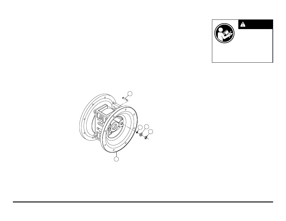
Step #2: Inspect the actuator
plungers.
See ILLUSTRATION AT RIGHT.
The actuator plungers (items 25)
can be reached through the pilot valve
cavity in the intermediate assembly
(item 5).
Remove the plungers (item 25) from
the bushings (item 7) in each end of
the cavity. Inspect the installed o-ring
(items 22) for cuts and/or wear. Replace
the o-rings if necessary. Apply a light
coating of grease to each o-ring and
re-install the plungers in to the bushings.
Push the plungers in as far as they
will go.
To remove the bushings (item 7),
first remove the retaining rings (item
26) by using a flat screwdriver.
NOTE:
It is recommended that new retaining
rings be installed.
Step #3: Re-install the pilot valve
assembly into the intermediate assembly.
Be careful to align the ends of
the stem between the plungers when
inserting the stem of the pilot valve into
the cavity of the intermediate.
Re-install the gasket (item 18),
air inlet cap (item 8) and capscrews
(item 11).
Connect the air supply to the pump.
The pump is now ready for operation.
ACTUATOR PLUNGER SERVICING
25
22
7
26
5
Read these instructions
c om ple t e ly, be f or e
installation and start-up.
It is the responsibility of
the purchaser to retain
this manual for reference. Failure to
comply with the recommendations stated
in this manual will damage the pump, and
void factory warranty.
IMPORTANT