Air distribution valve assembly drawing, Atex compliant air distribution valve servicing, Important – SANDPIPER S05 User Manual
Page 13
s05nmdl2sm-rev0614
sandpiperpump
.
com
Model S05 Non-Metallic •
10
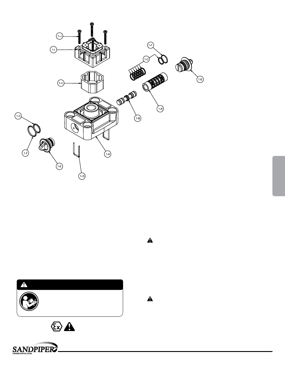
Air Distribution Valve Assembly Drawing
MAIN AIR VALVE ASSEMBLY PARTS LIST
Item
Part Number
Description
Qty
1
031.166.000
Air Valve Assembly
1
1-A
095.106.551
Body, Air Valve
1
1-B
031.132.000
Sleeve and Spool Set
1
1-C 560.101.360 O-Ring
8
1-E
165.122.551
End Cap
2
1-F 560.026.360 O-Ring
2
1-G
675.062.115
End Cap Retainer
2
1-H
530.031.550
Muffler
1
1-I
165.109.551
Muffler Cap
1
1-J
710.011.115
Self-Tapping Screw
4
For Pumps with Virgin PTFE coated hardware:
1
031.166.002
Air Valve Assembly
1
1-G
675.062.308
End Cap Retainer
2
1-J
710.011.308
Self Tapping Screw
4
(Includes all other items used on 031.166.000 above)
For Pumps w/ alternate Mesh, Sound Dampening or Piped Exhaust:
1
031.168.000
Air Valve Assembly
1
(Includes all items used on 031.166.000 above minus 1.H, 1.I and 1.J)
MAIN AIR VALVE ASSEMBLY PARTS LIST
Item
Part Number
Description
Qty
1
031.166.003
Air Valve Assembly
1
1-A
095.106.559
Body, Air Valve
1
1-B
031.132.000
Sleeve and Spool Set
1
1-C 560.101.360 O-Ring
8
1-E
165.122.551
End Cap
2
1-F 560.026.360 O-Ring
2
1-G
675.062.115
End Cap Retainer
2
1-H
530.031.550
Muffler
1
1-I
165.109.559
Muffler Cap
1
1-J
710.011.115
Self-Tapping Screw
4
For Pumps with alternate Mesh Muffler or Piped Exhaust:
1
031.168.002
Air Valve Assembly
1
(Includes all items used on 031.166.003 above minus 1.H, 1.I and 1.J)
For pumps with High Temperature Options:
1
031.194.000
Air Valve Assembly
1
1-B
031.175.000
Sleeve and Spool Set
1
(Includes all the other items on 031.168.000 above)
1
031.195.000 Air Valve Assembly
1
1
031.175.000
Sleeve and Spool Set
1
(Includes on other items on 031.166.000 above)
ATEX Compliant
Air Distribution Valve Servicing
See repair parts drawing, remove screws.
Step 1: Remove end cap retainer (1-G).
Step 2: Remove end cap (1-E).
Step 3: Remove spool part of (1-B) (caution: do not scratch).
Step 4: Press sleeve (1-B) from body (1-A).
Step 5: Inspect O-Rings (1-C) and replace if necessary.
Step 6: Lightly lubricate O-Rings (1-C) on sleeve (1-B).
Step 7: Press sleeve (1-B) into body (1-A).
Step 8: Reassemble in reverse order, starting with step 3.
Note: Sleeve and spool (1-B) set is match ground to a specified clearance
sleeve and spools (1-B) cannot be interchanged.
IMPORTANT
Read these instructions completely, before installation
and start-up. It is the responsibility of the purchaser
to retain this manual for reference. Failure to comply
with the recommendations stated in this manual will
damage the pump, and void factory warranty.
4: AIR
END