RIKON Power Tools 70-300 User Manual
Page 7
7
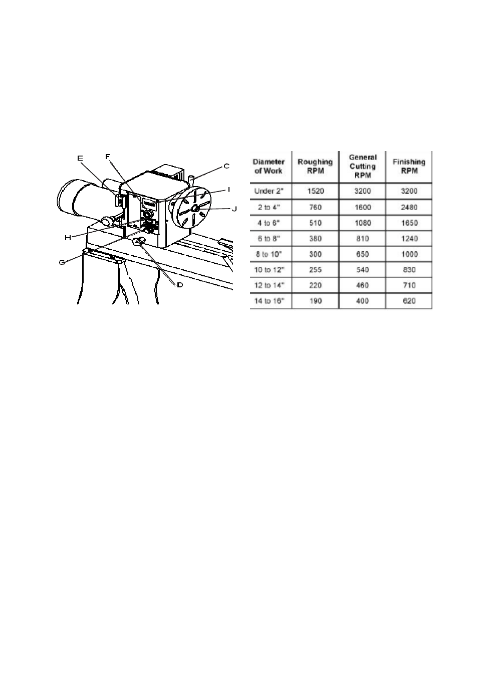
Fig. 3
Fig. 4
7.
Headstock RPM Readout: (I, Fig. 3) Displays the spindles RPM, see Figure 4.
8.
Headstock Spur Center: (J, Fig. 3) Used for turning between centers. Spindle taper is MT-2.
Remove spur center by inserting drift rod through the opposite end of the spindle and knocking spur
center out.
9.
Headstock Faceplate: (K, Fig. 3) Used for turning bowls and plates. There are a number of screw
holes for mounting the work piece. Thread the faceplate onto the spindle in a clockwise direction, and
tighten two set screws. Remove the faceplate by loosening two set screws. Push in headstock spindle
lock and use the provided rod in faceplate holes to unthread the faceplate.
10.
Headstock Indexing Hole: (L, Fig. 5) Thread indexing pin into the indexing hole making sure that
it locates in the spindle hole. There are 12 holes in the spindle 30° apart. There are three holes in the
headstock casting that accept the indexing pin. These holes are 20° apart. The combination of holes
will allow you to mark your workpiece for evenly spaced features. CAUTION! Never start the lathe
with the index pin engaged in the spindle!
11.
Tool Rest Body Lock Handle: (M, Fig. 6) Locks the tool rest body in position. Unlock handle to
position the tool rest in any location along lathe bed. Tighten handle when properly positioned.
12.
Tool Rest Lock Handle: (N, Fig. 6) Locks the tool rest in position. Unlock the handle to position
tool rest at a specific angle, or height. Tighten handle when properly positioned.
4. Headstock On/Off Button: (F, Fig.3) Pull the button out to turn “ON” the lathe. Push the button in to
turn the lathe “OFF”.
5. Headstock RPM Knob: (G, Fig. 3) Turn knob to desired RPM. There are two speed ranges offering
“speed” (0-3200) and “torque” (0-1200).
6. Headstock For/Rev Switch: (H, Fig. 3) Use the toggle switch to change the direction the spindle
turns. Only change direction when the spindle has stopped.