Assembly – RIKON Power Tools 10-370 User Manual
Page 9
9
Figure 5
A
Assembly
Installing the Switch Box Cont.
Mount the switch by using the corresponding holes
(A-Fig.5) in the back of the switch box. Use screws that
were removed from the frame shown in Fig.3. to mount
switch box to the column.
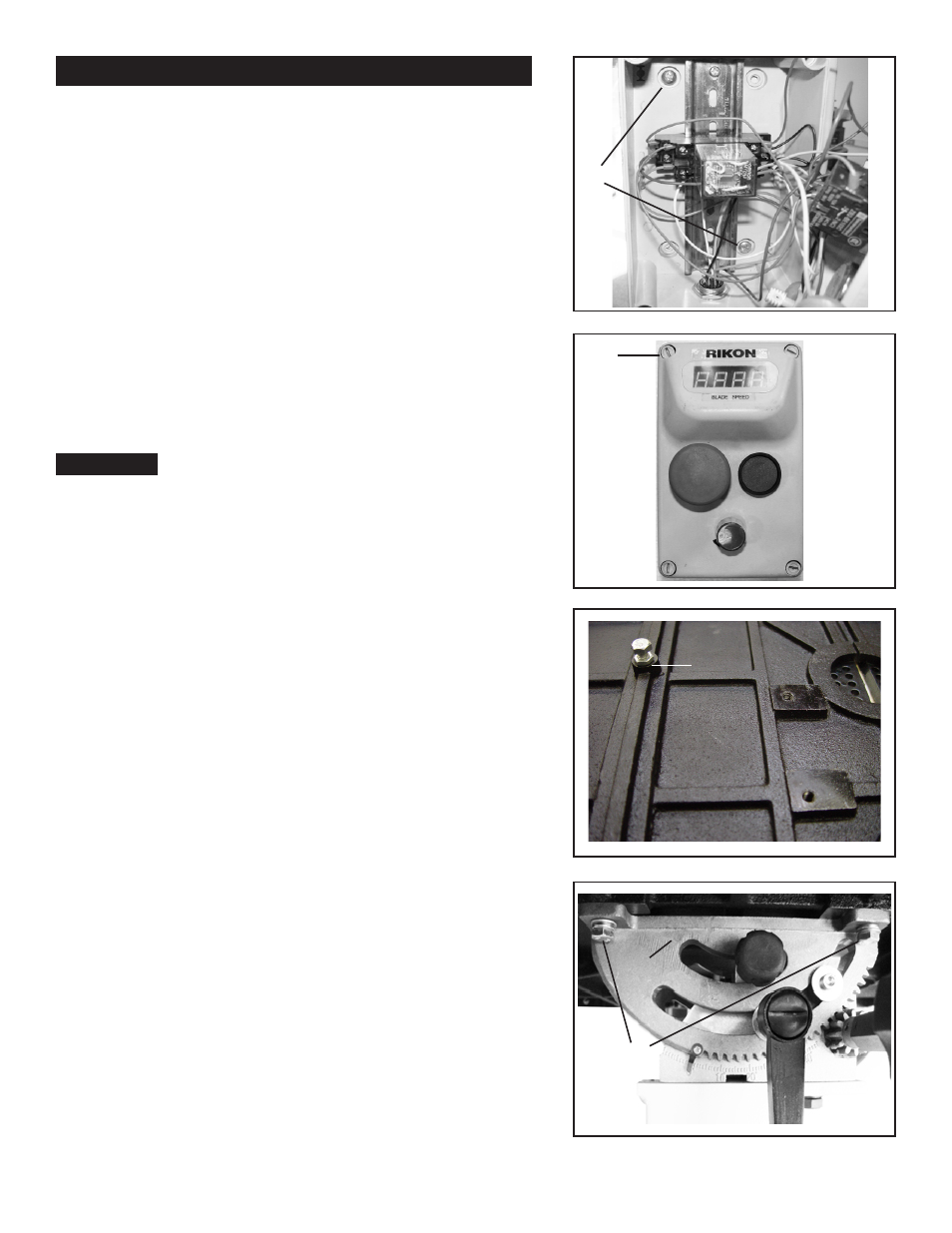
Next, install the control panel to the switch box. Make
sure that wires in the switch box do not become cut or
pinched while intalling the control panel. Tighten the four
control panels screws (A-Fig.6) with a flat-head screw
driver.
Take extra care when handling the control panel as
wires are attached to the switch box. Do not allow the
control panel to be supported or hang by the wiring as
damage can occur to the electronics.
Work Table Assembly
Installing 90° table stop:
Thread screw (M8x25) and nut (M8-1.25) to the bottom
of the table. (Shown Fig.7A)
With the help of another person, lift the work table onto
the trunnion (A-Fig.8).
Mount the work table to the trunnion using the supplied
(4) hex bolts, (4) lock washers and (4) washers
(B-Fig.8).
Caution!
A
Figure 6
Figure 7
Figure 8
Underside of Table
A
B
A