Assembly, Adjustments – RIKON Power Tools 10-370 User Manual
Page 11
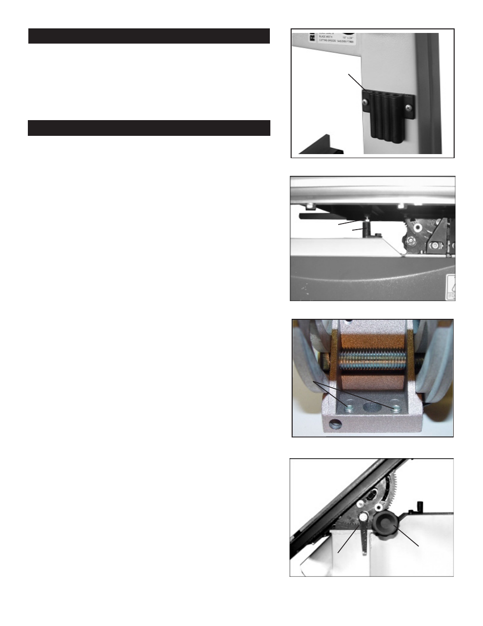
Storage for the “L” wrenches is provided for quick
access when adjustments are needed.
Place the (4) “L” wrenches (3mm, 4mm, 5mm and 6mm)
in the tool holder on the rear column support (Fig.13).
Setting the Table Square to Saw Blade
The table may be set at 90° to the saw blade sides
by adjusting the table stop screw under the table. The
table stop screw rests on the top of the quick release
adjustment stop. By first loosening the locking nut
(A-Fig.14) and then adjusting the screw (B-Fig.14), the
table can be set correctly. Retighten the locking nut
(A-Fig.14) making sure that the setting is maintained.
The table may also be set at 90° to the back of the saw
blade by adjusting the four trunnion micro adjustment
screws (A-Fig.15). First, slightly loosen part #98 (refer to
parts explosion on page 18
of this manual). Using the
3mm “L” wrench, turn the rear trunnion micro adjusting
screws part #125. Turning the screws clockwise will
raise the trunnion; counterclockwise will lower. Check
table for 90° and tighten part #98.
(Trunnion has been removed from bandsaw for clarity. Micro
adjusting screws are raised to exaggerate location. Only two of the
four micro adjusting screws shown.)
Tilting the Table
Loosen the lock handle (A-Fig.16) on the table trunnion.
Turn the table tilting knob (B-Fig.16) to adjust the table
to the desired angle. Use the angle indicator scale on
the trunnion bracket to find the desired angle. Retighten
the lock handle to secure the table.
Assembly
Figure 13
11
Figure 14
Tool Holder
Adjustments
A
B
Figure 15
Figure 16
A
B
A