Operation – Lincoln Electric IM954 VANTAGE 500 DEUTZ User Manual
Page 24
B-7
OPERATION
B-7
The VANTAGE® 500 DEUTZ and any high frequency
generating equipment must be properly grounded.
See the K930-2 TIG Module operating manuals for
complete instructions on installation, operation, and
maintenance.
When using the TIG Module, the OUTPUT control on
the VANTAGE® 500 DEUTZ is used to set the maxi-
mum range of the CURRENT CONTROL on the TIG
Module or an Amptrol if connected to the TIG Module.
VANTAGE® 500 DEUTZ SETTINGS WHEN USING
THE K930-2 TIG MODULE
• Set the WELD MODE switch to the “Touch Start TIG
20-250 Setting”.
• Set the IDLER switch to the “AUTO” position.
• Set the WELDING TERMINALS switch to the
“Remotely Controlled” position. This will keep the
solid state contactor open and provide a “cold” elec-
trode until the triggering device (Amptrol or Arc Start
Switch) is pressed.
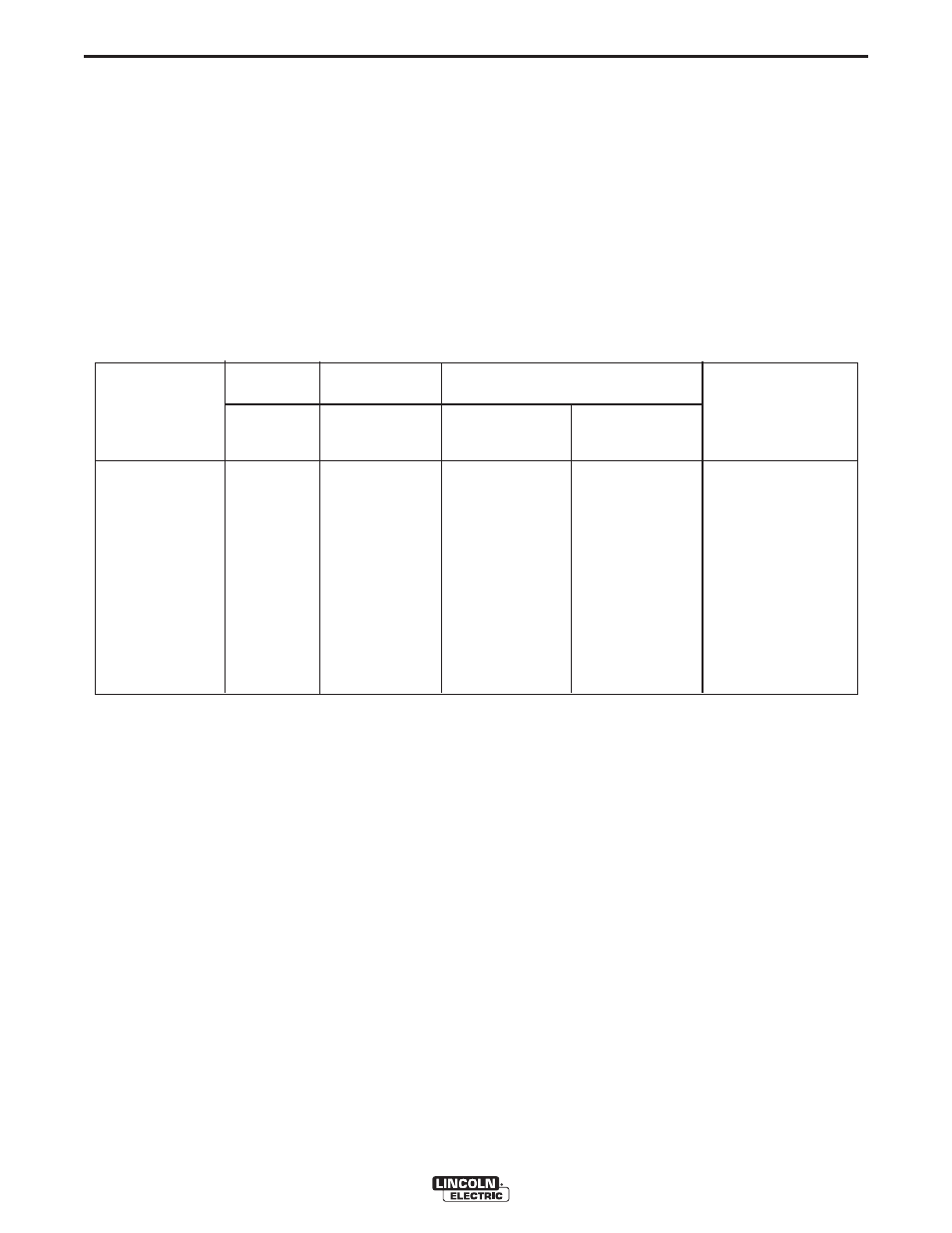
VANTAGE® 500 DEUTZ
Table B.3 TYPICAL CURRENT RANGES
(1)
FOR TUNGSTEN ELECTRODES
(2)
DCEN (-)
DCEP (+)
Approximate Argon Gas Flow Rate
l/min (c.f.m.)
Tungsten
Electrode
1%, 2%
1%, 2%
TIG TORCH
Diameter
Thoriated
Thoriated
Aluminum
Stainless Steel
Nozzle
mm (in)
Tungsten
Tungsten
Size (4), (5)
.25 (0.010)
2-15
(3)
2-4 (3-8)
2-4 (3-8)
#4, #5, #6
.50 (0.020)
5-20
(3)
3-5 (5-10)
3-5 (5-10)
1.0 (0.040)
15-80
(3)
3-5 (5-10)
3-5 (5-10)
1.6 (1/16)
70-150
10-20
3-5 (5-10)
4-6 (9-13)
#5, #6
2.4 (3/32)
150-250
15-30
6-8 (13-17)
5-7 (11-15)
#6, #7, #8
3.2 (1/8)
250-400
25-40
7-11 (15-23)
5-7 (11-15)
4.0 (5/32)
400-500
40-55
10-12 (21-25)
6-8 (13-17)
#8, #10
4.8 (3/16)
500-750
55-80
11-13 (23-27)
8-10 (18-22)
6.4 (1/4)
750-1000
80-125
13-15 (28-32)
11-13 (23-27)
(1)
When used with argon gas. The current ranges shown must be reduced when using argon/helium or pure helium shielding gases.
(2)
Tungsten electrodes are classified as follows by the American Welding Society (AWS):
Pure EWP
1% Thoriated
EWTh-1
2% Thoriated
EWTh-2
Though not yet recognized by the AWS, Ceriated Tungsten is now widely accepted as a substitute for 2% Thoriated Tungsten in AC
and DC applications.
(3)
DCEP is not commonly used in these sizes.
(4)
TIG torch nozzle “sizes” are in multiples of 1/16ths of an inch:
# 4 =
1/4 in.
6 mm
# 5 =
5/16 in.
8 mm
# 6 =
3/8 in.
10 mm
# 7 =
7/16 in.
11 mm
# 8 =
1/2 in.
12.5 mm
#10 =
5/8 in.
16 mm
(5)
TIG torch nozzles are typically made from alumina ceramic. Special applications may require lava nozzles, which are less prone to
breakage, but cannot withstand high temperatures and high duty cycles.