Electrical input connection, Warning, Electrical installation for pro-cut 40 – Lincoln Electric IM422 PRO-CUT 40 User Manual
Page 9: Capacitor discharge procedure, Input voltage setup power cord connection
ELECTRICAL INPUT CONNECTION
Electrical Installation for PRO-CUT 40
a. The PRO-CUT 40 should be connected only by a qualified
electrician. Installation should be made in accordance with
the U.S. National Electrical Code, all local codes and the
information detailed below.
b. When received directly from the factory, the dual voltage
(208-230) machines are internally connected for the highest
voltage (230) input. If 230 is the desired input, then the
machine may be connected to the power system without
any setup required inside the machine.
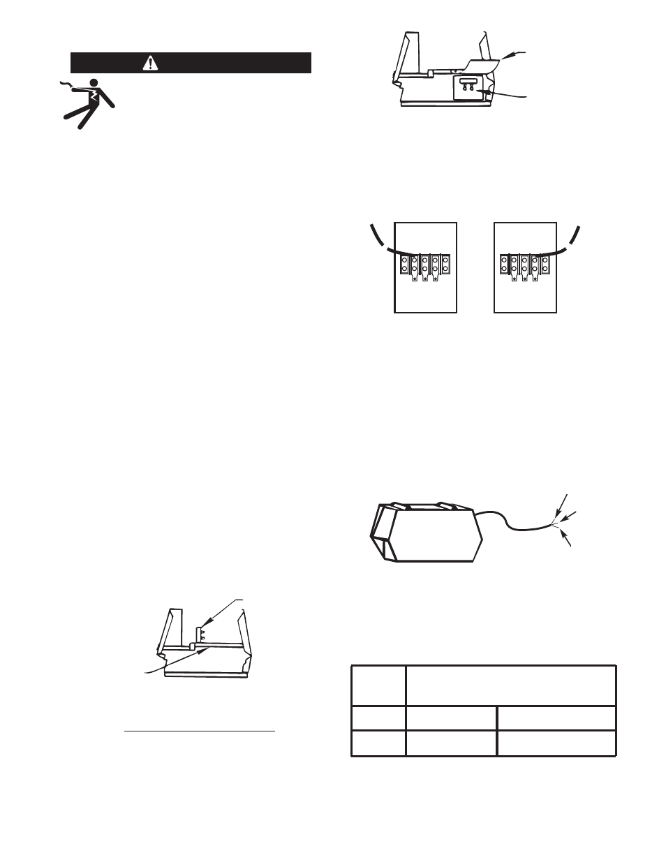
c. 208 volt operation requires a voltage panel setup: Remove
roof, discharge input capacitors, and move lead “A” from
“230” to “208” of terminal strip “1”. See following instruc-
tions.
NOTE: Do not power the PRO-CUT 40 off of the auxiliary power
supply of an engine driven welder. If the voltage peaks
from the engine welder exceed 380V the filter capaci-
tors, FETS of other circuity may fail on the PRO-CUT 40.
Capacitor Discharge Procedure
a. Locate discharge resistor (25 ohms 25W)
attached to fan baffle. Resistor has no leads
connected to it.
b. Remove resistor from fan baffle.
c. Hold resistor body with electrically insulated
glove. DO NOT TOUCH TERMINALS.
Carefully lift mylar insulation. Connect resistor
terminals across two hex head cap screws in
position shown. Hold in position for 1 second.
Repeat for capacitor located on opposite side.
d. Use a DC voltmeter to check that voltage is not
present across terminals.
e. Replace discharge resistor onto fan baffle.
Input Voltage Setup
Power Cord Connection
A 10-foot power cord is provided and wired into the
machine. Follow the power cord connection instruc-
tions. Incorrect connection may result in equipment
damage.
Install in accordance with all local and national electric
codes.
RECOMMENDED FUSE SIZES
BASED ON THE U.S. NATIONAL ELECTRICAL CODE
AND MAXIMUM MACHINE OUTPUTS
INPUT VOLTS*
FUSE SIZE IN AMPS
(TIME DELAY FUSES)
1 Phase
208
60
60 Hz / 50 Hz
230
60
* Input voltage must not exceed ± 10% of rated value.
– 9 –
ELECTRIC SHOCK can kill.
• Disconnect input power before
proceeding.
• Have a qualified electrician make
the input connections.
• Be sure to discharge capacitors with the
procedure outlined below before working in
that area of equipment.
------------------------------------------------------------
WARNING
RESISTOR
FAN BAFFLE
LIFT MYLAR
INSULATION
CAPACITOR
TERMINALS
208
230
H1
H3
TERMINAL STRIP 1
208V INPUT
208
230
H1
H3
TERMINAL STRIP 1
230V INPUT
A
A
BLACK
GREEN
WHITE