Troubleshooting, Caution – Lincoln Electric IM986 POWER WAVE i400 User Manual
Page 51
E-14
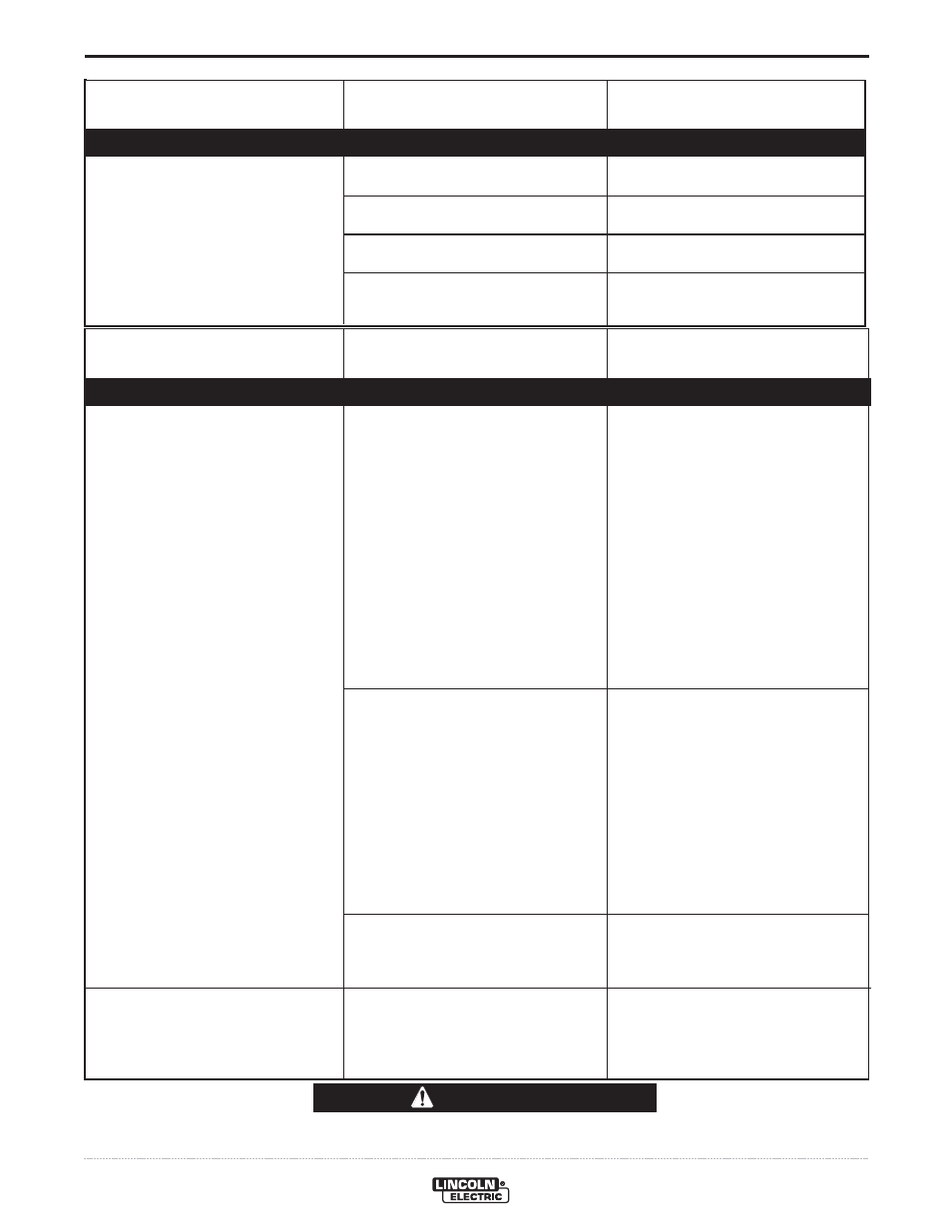
TROUBLESHOOTING
E-14
POWER WAVE® i400
If for any reason you do not understand the test procedures or are unable to perform the tests/repairs safely, contact your
Local Lincoln Authorized Field Service Facility for technical troubleshooting assistance before you proceed.
CAUTION
PROBLEMS
(SYMPTOMS)
POSSIBLE
CAUSE
RECOMMENDED
COURSE OF ACTION
ETHERNET
Cannot Connect.
Connection Drops while welding.
1. Physical connection.
2. IP address information.
3. Ethernet Speed.
1. Cable Location.
1. Verify that the correct patch cable or
cross over cable is being used (refer
to local IT department for assis-
tance).
NOTE:
• For direct connection to the Fanuc
R30iA Controller, use only the cable
provided with the K2677-1 Integration
kit
• Verify the cables are fully inserted
into the bulk head connector.
• LED 8 located under the PC board
ethernet connector will be lit when
the machine is connected to another
network device.
2. Use Weld Manager (included on the
POWER WAVE® Utilities and
Service Navigator CDʼs or available
at www.powerwavesoftware.com) to
verify the correct IP address infor-
mation has been entered.
NOTE:
• The IP address configuration MUST
be set to dynamic when connected to
the Fanuc R30iA Controller.
• Verify no duplicate the IP addresses
exist on the network.
3. Verify that the network device con-
nected to the POWER WAVE® is
either a 10-baseT device or a
10/100-baseT device.
1. Verify Network cable is not located
next to current carrying conductors.
This would include input power
cables and welding output cables.
PROBLEMS
(SYMPTOMS)
POSSIBLE
CAUSE
RECOMMENDED
COURSE OF ACTION
DeviceNet – PLC Controlled System
Bad Welding.
4. Limit Errors
5. Gas
6. Welding set points
7. Wire Drive / Gear selection
4. Verify all welding setpoint values
are within limits.
5. Verify Gas remains on until after
the weld is complete.
6. Verify welding set points for work
point, trim, and wave values.
7. Verify proper wire drive and gear
ratio has been selected
Observe all Safety Guidelines detailed throughout this manual