Installation, Electric shock can kill, Connection for negative polarity welding – Lincoln Electric IM697 RED-D-ARC MX 300 User Manual
Page 14: Power source setup, Warning, Caution
A-7
INSTALLATION
A-7
RED-D-ARC MX350
Table .1
Converters
Cable Size
on Cable
AWG (mm2 )
1
1/0 (50)
2
2/0 (70)
3
3/0 (95)
4
4/0 (120)
5
2x3/0 (2x95)
The output "Electrode" cable should be 2/0 AWG
(70mm
2
) if sized for rated output up to 200 ft.(61m)
from the Converter. If paralleled, the output cable to
the arc should be 4/0(120mm
2
).
ELECTRIC SHOCK can kill.
Do not disconnect the Work clip lead
without first switching OFF the
Converter panel switch. Failure to do
so will allow the work lead clip to be
electrically "hot" to work, and "hot" to
the electrode, through the circuit of
the Converter for about 5 seconds until the input
contactor opens.
------------------------------------------------------------------------
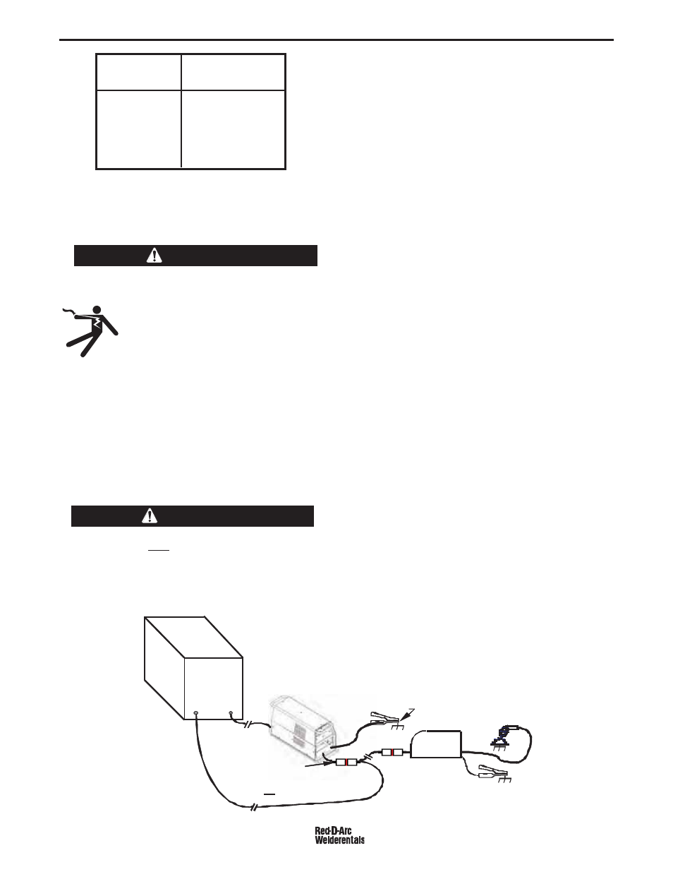
CONNECTION FOR NEGATIVE
POLARITY WELDING
(See Figure 2A)
A RED-D-ARC MX350 may be used for Negative
(straight) polarity CV (Innershield) or CC processes if
connected per the diagram shown below:
No more than one RED-D-ARC MX350 may be
connected to a power source for Negative Polarity
welding. Multiple units connected to the same
power source may cause damage to the RED-D-
ARC MX350.
------------------------------------------------------------------------
This connection method will only permit using one
RED-D-ARC MX350 arc on one power source, and
cables have to be run to the RED-D-ARC MX350 from
both (+) and (-) output studs of the power source. This
is required so that the (-) electrode has a return path
to both the RED-D-ARC MX350 and the Power
Source, just like the normal (+)polarity connection has
a (-) return path to both the RED-D-ARC MX350
(through the Work Clamp) and to the Power Source
(through work connections). Both cable sizes are the
same, with capacity as recommended for normal (+)
connection.
If the power source itself can not perform the CV
negative welding process, the RED-D-ARC MX350 is
basically serving very well as a process converter (ei;
CV from a CC power source), as well as a remote
output control. The advantage is that the same
equipment (RED-D-ARC MX350ʼs and CC Power
Sources) are used for all weld process applications.
POWER SOURCE SETUP
Refer to the Instruction Manual provided with the
Multi-Source power source, or other DC power source
being used, for input power supply connections,
output connections and controls setup.
In general:
1. Connect the positive (+) output connection terminal
to the input supplying the RED-D-ARC MX350 sys-
tem, and the negative (-) output connection termi-
nal to the work. (see Figure 1).
2. If not using a Multi-Source power source;
a If an inductance control, or tap, is selectable,
use lowest inductance.
b. Use CC (Constant Current) mode, for maximum
supply voltage.
c. Set panel output control to maximum, for maxi-
mum current capacity.
d. Activate output with the "output terminals on"
switch, or jumper (2-4 on LE Co terminal strips).
WARNING
-
+
W
Wor
ork
Wor
ork
LN-25 Wire
LN-25 Wire
Feeder
Feeder
W
Wor
or k
(-)
(-) Work Lead
ad
t o
(-)
(-) P
Pow
ower
r Sou
ourc
rce s
stu
tud
and
nd
(-)
(-) Electrode Lead
Electrode Lead
MX350
MX350
MX350
MX350
(+)
) Out pu
put Lea
Lead
to
o W ork
MX350
MX350
Negative Polarity
Negative Polarity
DC
DC
POWER
POWER
SOURCE
SOURCE
CAUTION
Figure 2A