Installation, A-4 remote output control options, Cv mode wire welding – Lincoln Electric IM697 RED-D-ARC MX 300 User Manual
Page 11: Cc mode stick welding and gouging, Quick-connect "pig-tails, Attachment and arrangement of "pig- tails
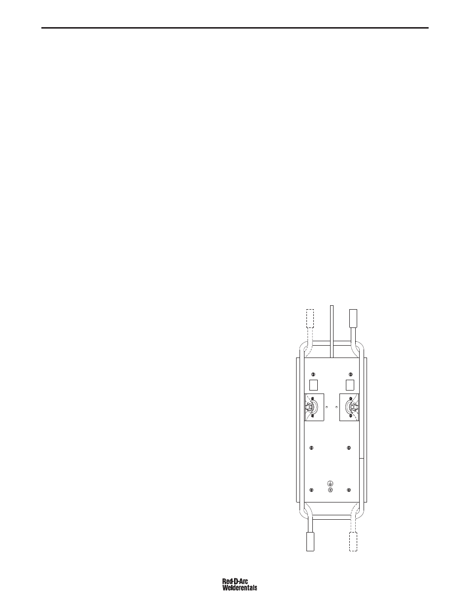
BOTTOM VIEW
TO ELECT.
TO ELECT.
TO
WORK
TO POWER
SOURCE
TO POWER
SOURCE
+
INPUT
+
ELECTRODE
ELECT.
+
ELECT.
+
+
IN
+
IN
A-4
INSTALLATION
A-4
REMOTE OUTPUT CONTROL OPTIONS
The RED-D-ARC MX350 is provided with a 3-pin remote
receptacle.
CV MODE WIRE WELDING
The Converter in CV mode was designed for use with
an arc-powered wire feeder like the LN-25. The
Converter output is always "hot" when the mode
switch is not OFF, so it is recommended that the LN-
25 model be equipped with the internal contactor in
order to have a "cold" electrode when the gun trigger
is released.
The CV mode recommended processes are positive
(+) polarity wire welding within the output capacity of
the Converter, including:
Flux Cored Arc Welding (FCAW)
Innershield:
NS3M (5/64”-3/32”)
NR305 (.068”)
Outershield:
OS-70 (1/16”-5/64”)
OS-71 (.045”-1/16”)
MC-710 (.045”-5/64”)
Gas Metal Arc Welding (GMAW)
Carbon Steel: L50/56 (.030”-1/16”)
CC MODE STICK WELDING AND
GOUGING
The CC mode recommended processes are positive
(+) polarity stick and arc gouging within the output
capacity of single, or paralleled, Converters; including:
Shielded Metal Arc Welding (SMAW)
E6010/6011:
FW5P/180 (3/32”-1/4”) "fast-freeze"
E6013: FW37 (3/32”-3/16”)
"fill-freeze"
E7010/8010: SA85/70+ (3/32”-7/32”)
"fast-freeze" HT pipe
E7018/7028: JW LH70/3800 (3/32”-
5/32”)
"low-hydrogen"
E7024/6027:
JW1,3/2 (1/8”-5/16”)
"fast-fill"
Arc Air Carbon (AAC)
Gouging:
Carbons (5/32”-3/8”)
INSTALLATION
QUICK-CONNECT "PIG-TAILS"
The RED-D-ARC MX350 is factory provided with two 21
in.(53 cm) long 2/0 AWG (70mm2 ) "pig-tail" cables with
their 0.5"(13mm) hole lug ends routed through the "INPUT +
"(on back) and "ELECTRODE + "(on front) cable channels
of the Converter and attached to the bottom-accessed cov-
ered cable connection studs.
Attach the preferred standard user-provided Quick-connect
terminal (such as Lincoln Twist-Mate or Tweco 2-MPC type)
to the cut-off end of these cables. Use the female connector
on the "ELECTRODE +" cable and the male connector on
the "INPUT +" cable.
ATTACHMENT AND ARRANGEMENT OF "PIG-
TAILS"
To best suit the desired inter-connection of the Converters
the "pig-tail" cables may be routed into the front cable chan-
nels, and/or into the back for single or double "pig-tail"
cables to the bottom-accessed covered cable connection
studs. (See below and refer to Figures 1 and 2.):
RED-D-ARC MX350
FIGURE 1