Operation, Paralleled converters, Remote control of paralleled converters – Lincoln Electric IM664 Multi-Weld 350 Arc Converter User Manual
Page 17
B-3
OPERATION
B-3
Disconnecting the Remoteʼs plug from this recep-
tacle automatically transfers output control back
to the panel Output Control (item (2) above).
Remote output On/Off switching can also be
done thru this Remote Control receptacle. by per-
forming the following wiring changes:
1. Making sure the input to the Converter is
removed, remove the case wraparound.
2. Locate the 4-pin plug (P21) on the back
panel of the control box module, and cut the
jumper lead looping from the back of the
plug. (Refer to the Wiring Diagram in this
manual.) Insulate the cut lead ends and
leave long enough to possibly splice back
together again at some future time.
3. Replace the case wraparound.
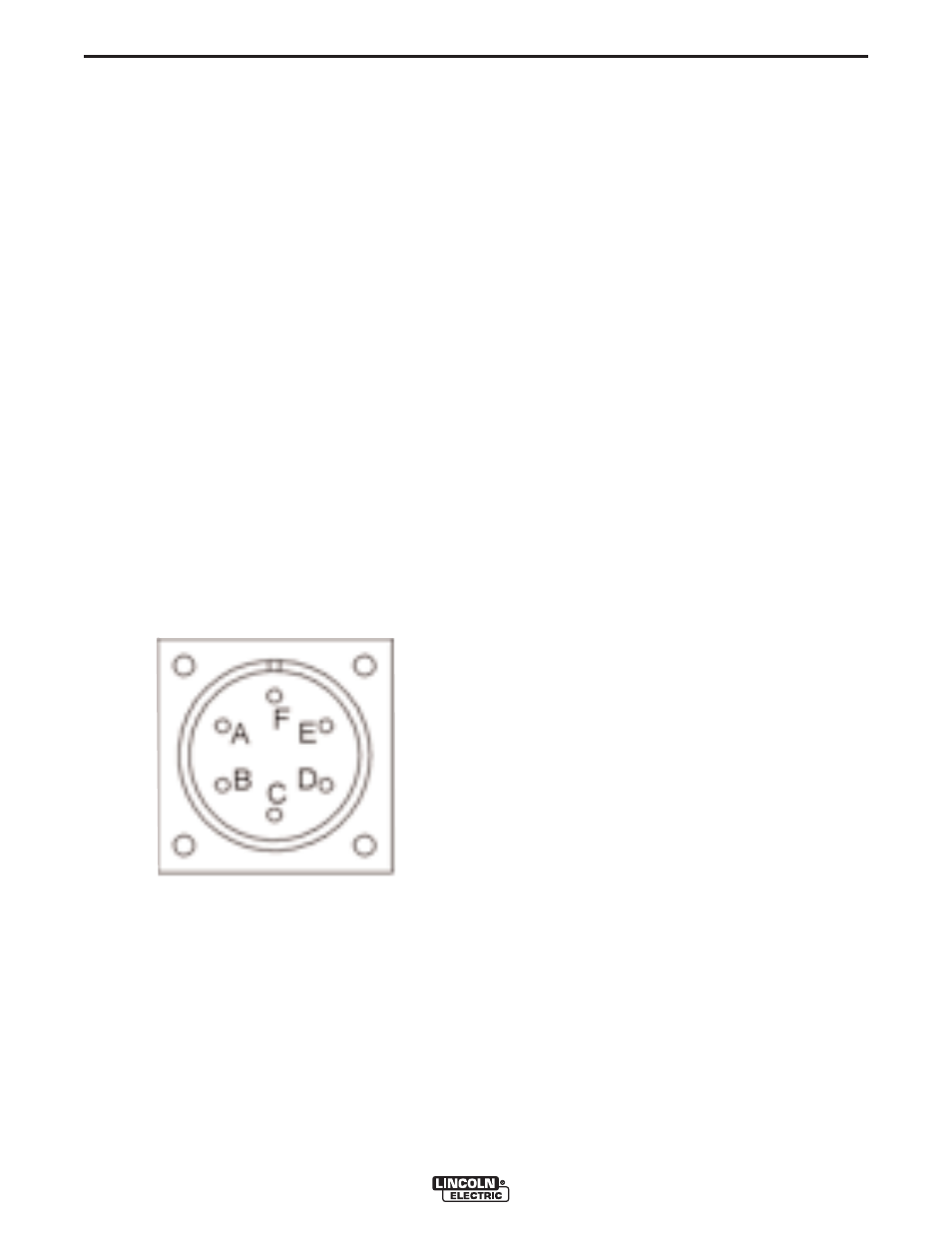
4. Connect a user-provided remote switch
between pins D and E of an MS3106A-18-
12P plug (Lincoln part no. S12020-27 with
S12024-1 cable clamp). See diagram
below:
Pin:
Remote Function:
A
Max. of 10K pot
B
Wiper of 10K pot
C
Min. of 10K pot
D
Output Switch
E
Output Switch
F
No connection
5. Connect this switch plug to the Multi-Weld
350 Remote Control Receptacle (10) with
switch opened. Closing the switch activates
the Converter output.
PARALLELED CONVERTERS
Multi-Weld 350 converters that are paralleled (see
INTER-CONNECTION OF CONVERTERS in the
INSTALLATION section) must each be set up in the
same manner in order to manage the arc current
drawn from each:
1) Set to CC mode with CC SLOPE switch set to
STICK/GOUGE.
2) Preset Output Controls of both paralleled
Converters to ~1/2 desired total Amps.
If arc current from each Converter gets too out of bal-
ance (primarily a problem if trying to use CV mode)
the hotter running Converter could go into current-lim-
iting and/or Thermal shutdown (See OVER-TEMPER-
ATURE SHUTDOWN in the INSTALLATION section),
which might then overload the other, or at least inter-
rupt the operatorʼs process. However, no damage will
occur to the Converters.
REMOTE CONTROL OF
PARALLELED CONVERTERS
(FOR CC STICK/GOUGE MODE ONLY)
Full Range remote control can be accomplished with a
separate optional Remote output control (see
INSTALLATION section) connected to each
Converter. The current contribution of each Converter
will depend on its remote output setting.
Partial Range remote control can be accomplished
with a single Remote Control connected to the output
Converter with the input Converter preset with its
panel Output Control to below the minimum desired
output range. The Remote Control, connected to the
output Converter, will control its output to add to the
preset level.
Remote Output On/Off switching maybe setup for
each of the paralleled Converters, but isolated, or
double-pole, switches must be used to activate each
separately but simultaneously.
MULTI-WELD 350