Installation, Attachment and arrangement of "pig-tails, A-4 remote output control options – Lincoln Electric IM664 Multi-Weld 350 Arc Converter User Manual
Page 11: Cv mode wire welding, Cc mode stick welding and gouging, Quick-connect "pig-tails
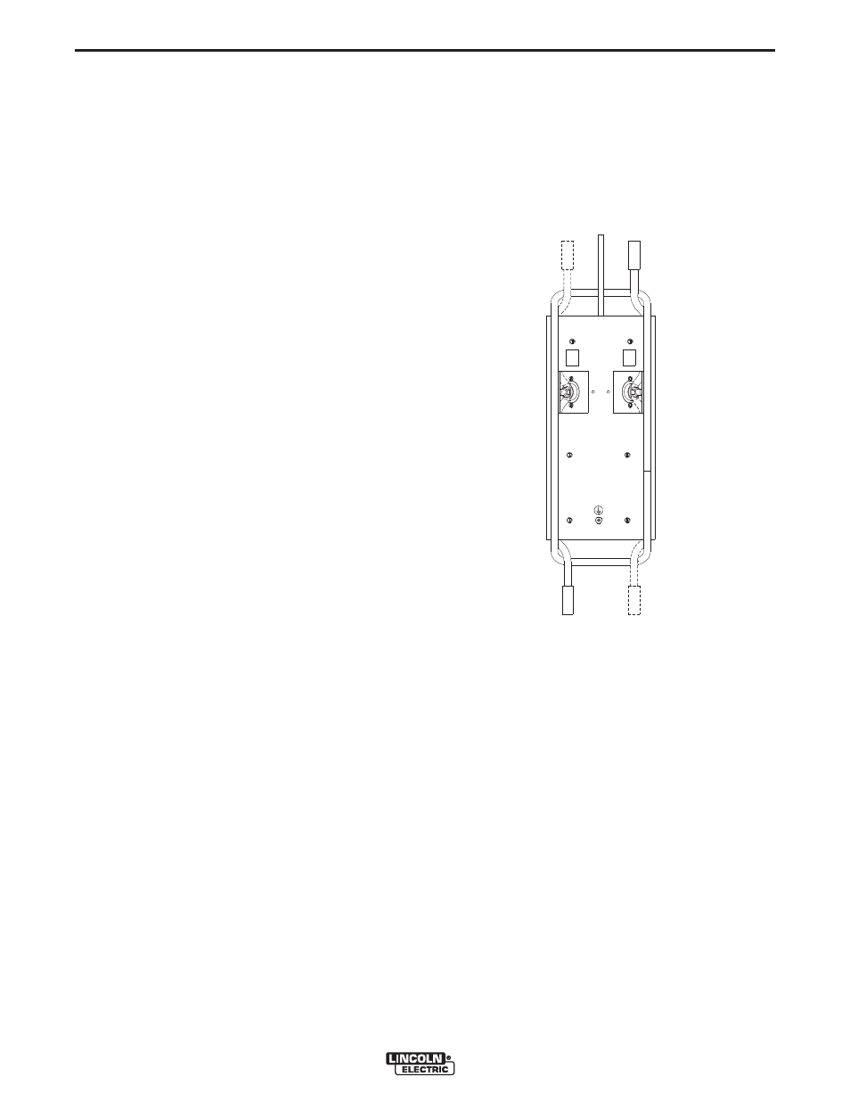
ATTACHMENT AND ARRANGEMENT OF
"PIG-TAILS"
To best suit the desired inter-connection of the
Converters the "pig-tail" cables may be routed into the
front cable channels, and/or into the back for single or
double "pig-tail" cables to the bottom-accessed cov-
ered cable connection studs. (See below and refer to
Figures 1 and 2.):
To connect the "pig-tail" cables to the Converter:
1. Stand the Converter vertically on its rear handle
and skid to gain access to the bottom stud
covers, then remove the two 0.25"(6.3mm)
screws securing each cover and fold out the
cover insulation.
2. Route the appropriate "pig-tail" cable lug ends
under the skid rail (for strain-relief) through the
desired front and/or rear corner channels to the
exposed 0.5"(13mm) stud, and remove the flange
nut with a .75"(19mm) wrench. Note: Input supply
cable(s) must connect through "INPUT +" labeled
channels, and output weld cable(s) must connect
through "ELECTRODE +" labeled channels.
3. Slip the "pig-tail" cable lug(s) over the stud and
re-secure the flange nut, making sure that lug(s)
nowhere touch any sheet metal of the stud hous-
ing, then fold back the cover insulation and
replace the stud cover.
BOTTOM VIEW
TO ELECT.
TO ELECT.
TO
WORK
TO POWER
SOURCE
TO POWER
SOURCE
+
INPUT
+
ELECTRODE
ELECT.
+
ELECT.
+
+
IN
+
IN
A-4
INSTALLATION
MULTI-WELD 350
A-4
REMOTE OUTPUT CONTROL OPTIONS
The Multi-Weld 350 is provided with a 6-pin remote
receptacle to permit use with the 25ft.(7.6 m) K857 or
100ft.(30.4 m) K857-1 Remote Output Control options,
or with the LN-25 equipped with the K444-1 Remote
Control option. These Remotes have single-turn reso-
lution on a Min to Max numbered dialplate.
CV MODE WIRE WELDING
The Converter in CV mode was designed for use with
an arc-powered wire feeder like the LN-25. The
Converter output is always "hot" when the mode
switch is not OFF, so it is recommended that the LN-
25 model be equipped with the internal contactor in
order to have a "cold" electrode when the gun trigger
is released.
The CV mode recommended processes are positive
(+) polarity wire welding within the output capacity of
the Converter, including:
CC MODE STICK WELDING
AND GOUGING
The CC mode recommended processes are positive
(+) polarity stick and arc gouging within the output
capacity of single, or paralleled, Converters; including:
QUICK-CONNECT "PIG-TAILS"
The Multi-Weld 350 is factory provided with two 21
in.(53 cm) long 2/0 AWG (70mm2 ) "pig-tail" cables
with their 0.5"(13mm) hole lug ends routed through
the "INPUT + "(on back) and "ELECTRODE + "(on
front) cable channels of the Converter and attached to
the bottom-accessed covered cable connection studs.
Attach the preferred standard user-provided Quick-
connect terminal (such as Lincoln Twist-Mate or
Tweco 2-MPC type) to the cut-off end of these cables.
Use the female connector on the "ELECTRODE +"
cable and the male connector on the "INPUT +" cable.