Lincoln Electric IM408 MAGNUM SG SPOOL GUN User Manual
Page 18
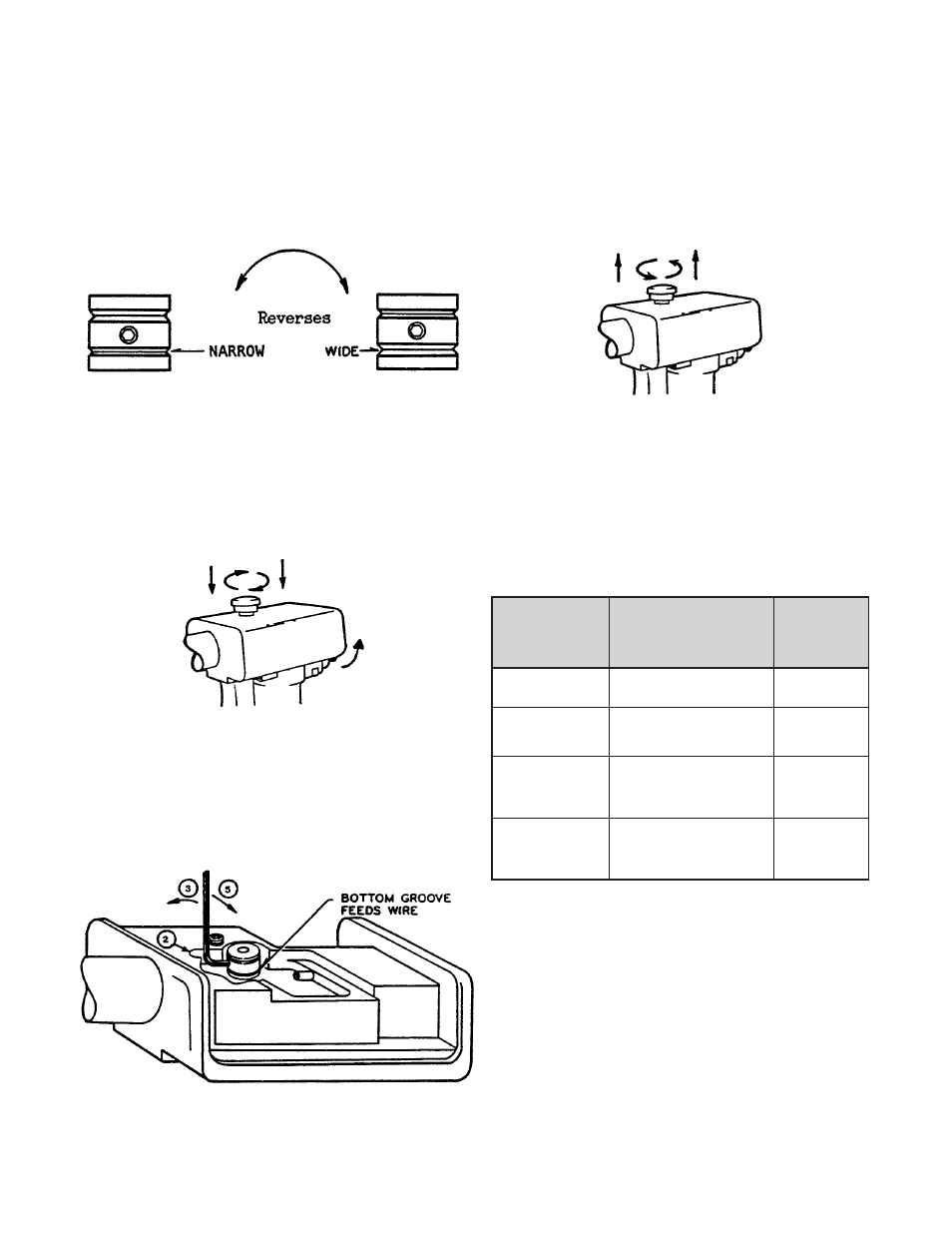
Drive Roll Groove Selection
The drive roll has two grooves, a wider and a
narrower one, to accommodate changes in wire
size used. Changing between the grooves simply
requires reversing the drive roll. The following
information is to be used to determine proper
g r o o v e p o s i t i o n i n g a n d t o c h a n g e i t , i f
necessary, for the wire size selected.
A. Drive Roll Orientation
4. Slide drive roll off motor shaft. Turn roller
over, end for end.
5. Slide drive roll back on motor shaft and
tighten set screw. Make sure set screw is
on flat part of motor shaft.
6. Remove Allen wrench and reinstall see-
through cover.
B. Changing Drive Roll Orientation
1. Move release lever to up position and
remove see-through body cover.
Oriented for .023-.035"
(0.6-0.9 mm) electrode
wire with smaller groove
in feed position.
Oriented for 3/64" (.045)
(1.2 mm) electrode wire
with larger groove in
feed position.
2. Rotate drive roll by jogging drive motor
with trigger switch and/or rotating with
fingertips until set screw lines up with slot
in body.
3. Insert 5/64" Allen wrench in set screw and
turn set screw just enough to loosen roller.
11
Setting Gas Flow Rate
Gas handling systems having adjustable flow valves
should be set for the following argon flow rates,
depending on base metal thickness and welding
position.
ARGON SHIELDING GAS FLOW RATES
Material
Flow
Thickness
Rates
in inches
Welding Position
in cf/hr
and (mm)
(l/min)
1/16 (1.6 mm)
Flat
25 cf/hr
(11.8 l/min)
3/32 to 3/16
Flat, Vertical, Horizontal,
30
(2.4 to 4.8 mm)
Overhead
(14)
Flat
30 (14)
1/4 to 3/8
Vertical, Horizontal
35 (16.5)
(6.3 to 9.5 mm)
Overhead
40 (18.9)
Flat
35 (16.5)
3/4 (19 mm)
Vertical, Horizontal,
40 (18.9)
Overhead
Test Weld Settings
For test weld procedures with other power
sources, refer to Part B, Section 2.4, “Procedure
Settings”, or use the following approximate
settings:
Welding Voltage
22-23V
Wire Feed Speed
250-350 ipm
(6.3 - 8.9 m/min)