Installation, Figure 3a figure 3b table 2 – Lincoln Electric IM439 MAGNUM COOLERS 20-I User Manual
Page 13
A-6
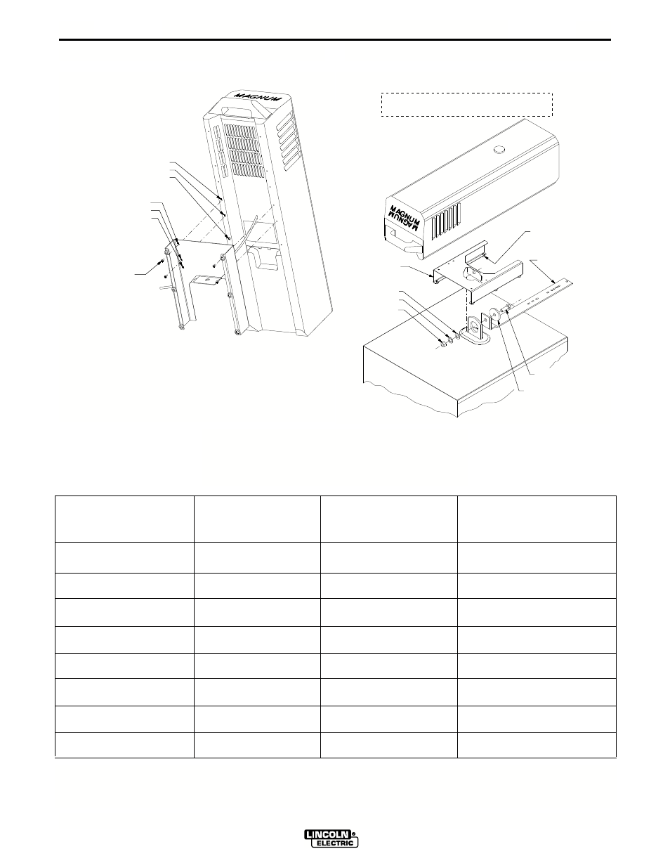
INSTALLATION
MAGNUM COOLER 10 & 20
A-6
2. Route all water line connections onto connection block at back of Cooler as outlined in the IM manual
provided with the Magnum Cooler.
S e l f T a p p i n g S c r e w
( 4 r e q ' d )
WARNING
ON COOLERS 20 & 20-I :
Align holes A & B of mounting bracket with holes A & B of Magnum Cooler. Secure bracket to the back
of Cooler with 4 self tapping screws provided.
1. ON COOLERS 10 & 10-I :
Align holes A & C of mounting bracket with holes B & C of Magnum Cooler. Secure bracket to the back
of Cooler with 4 self tapping screws provided.
B R A C K E T H O L E " A "
B R A C K E T H O L E " B "
C O O L E R H O L E " B "
C O O L E R H O L E " C "
B R A C K E T H O L E " C "
C O O L E R H O L E " A "
NOTE: FOR PROPER INSTALLATION WHEN USED WITH LINCOLN K835, K840,
K841 OR K842 UNDERCARRIAGES, THE RUBBER FEET MAY NEED TO BE
REMOVED FROM THE BOTTOM OF THE MOUNTING BRACKET.
D o o r B u m p e r
( F a c t o r y I n s t a l l e d )
( 6 r e q ' d )
S E E N O T E
M o u n t i n g B r a c k e t
( s h o w n d e t a t c h e d
f r o m C o o l e r b a c k
f o r c l a r i t y )
1 / 2 - 1 3 H e x N u t
1 / 2 - 1 3 x 1 . 5 0 H H C S
L a r g e P l a i n W a s h e r
* N O T R E Q ' D W H E N U S I N G
U N D E R C A R R I A G E O P T I O N
P l a i n W a s h e r
L o c k W a s h e r
POWER SOURCE
FRONT
O p t i o n a l
U n d e r c a r r i a g e A r m
FIGURE 3a
FIGURE 3b
TABLE 2
Recommended Magnum Cooler Use with Lincoln
Power Source / Undercarriage Combination
Figure 3
Power Source
Cooler
Undercarriage
Mtg. Bkt.
Scheme
CV-200
Cooler 10
K874
A
CV-250
Cooler 10 or 20**
K874
A or C
CV-300
Cooler 10 or 20**
K874
B or D
CV-400
Cooler 20
K841-1*
E
DC-400
Cooler 20
K841-1*
E
DC-600
Cooler 20
K842-1*
E
Pulse Power 500
Cooler 20
K842-1*
E
R3S-325
Cooler 20
K840-1
E
** Use 20 model for demanding welding applications.
* Not available at time of printing.