Installation, Warning – Lincoln Electric IM439 MAGNUM COOLERS 20-I User Manual
Page 10
A-3
INSTALLATION
MAGNUM COOLER 10 & 20
A-3
INSTALLATION
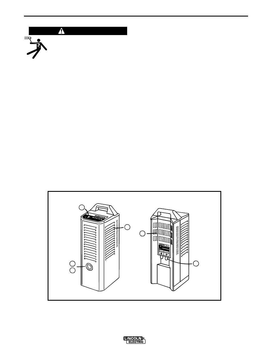
PRODUCT OVERVIEW
The LIGHTED POWER SWITCH is located at the left
side of the control panel (A). Cooler will be “ON” when
pressed to “I“.
Coolant INLET and OUTLET fittings are found at the
rear of the unit (B). They are welding industry stan-
dard English left-hand fittings for water coolant lines.
The right side fitting is marked “coolant out” (coolant
supply to the welding equipment); the left side fitting is
marked “coolant in” (coolant returning from the weld-
ing equipment).
The FILL CAP is at the front of the unit (C).
Cap removal: While pressing the bulls-eye
inward, grip the tab and remove the cap with
a peeling motion.
Cap replacement: Install by pressing inward on the
bulls-eye; the cap will “snap” into position.
The coolant FLOW INDICATOR is accessed by
removal of the fill cap. Actual return flow is directly vis-
ible, via the fill opening (D) with the unit in vertical or
horizontal position.
Air flow vents (E).
ELECTRIC SHOCK
can kill.
• Disconnect input power by removing
plug from receptacle before working
inside Cooler.
• Use only grounded receptacle.
• Do not remove the power cord ground prong.
• Do not touch electrically “hot” parts inside Cooler.
• Have qualified personnel do the installation, main-
tenance and troubleshooting work.
---------------------------------------------------------------------
WARNING
A
E
E
B
C
D
FIGURE 1