Installation – Lincoln Electric IM615 K1614-2,-3 MAGNUM 250 NR GUN & CABLE User Manual
Page 11
B-2
INSTALLATION
MAGNUM® 250 NR
B-2
K466-5 INSTALLATION (For L-Tec feeders equipped
with an L-Tec feeder connector assembly, MIG 35, MIG
31A, 225...)
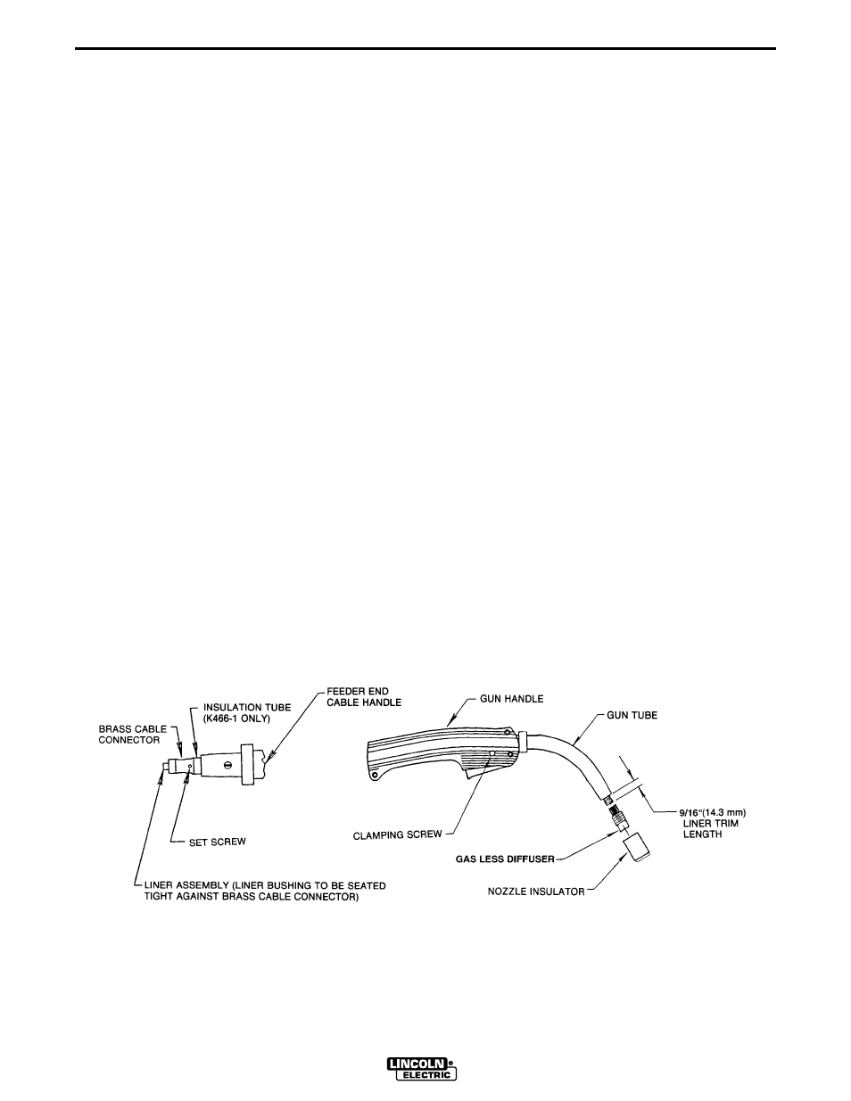
a. Remove brass cable connector (see Figure 1) from
the K466-5 kit and screw it onto the feeder end of
the gun cable. Tighten the connection with the
wrench provided.
b. For L-Tec machines that require trigger lead con-
nections to be made at a terminal strip located with-
in the machine (L-Tec 225), a gun control cable with
forked terminals is provided. Connect the terminat-
ed leads to the terminal strip. For a machine that
requires a twist-lock gun control cable connection,
continue to use the L-Tec gun control cable provid-
ed with the L-Tec wire feeder connector assembly.
Connect the twist-lock plug to the proper receptacle
on the machine
K466-6, K466-7 and K466-9 Installation (Wirematic,
Hobart Series 2000 Feeders and SP100T Type feed-
ers)
a. Remove brass cable connector (see Figure 1) from
the connector kit and screw it onto the feeder end of
the gun cable. Tighten the connection with the
wrench provided.
b. Attach the gun control cable provided to the trigger
connector on the front of the wire feeder.
LINER INSTALLATION
a. Lay the gun and cable straight on a flat surface.
b. Make sure that the set screw in the connector end
is backed out so as not to damage liner or liner
bushing. Remove and save the nozzle insulator, and
gas less diffuser from the end of the gun tube
assembly.
c. Insert a new untrimmed liner into the connector end
of the cable. Be sure the liner bushing is stenciled
appropriately for the wire size being used.
d. Fully seat the liner bushing in the connector and:
For all K466 connector kits except K466-3 and
K466-4, tighten the set screw in the cable connec-
tor.
or
For K466-3 and K466-4, screw in the connector cap
provided in the kit until it seats on the face of the
bushing. Then insert the appropriate piece of liner
material into the connector cap and tighten the set
screw. Three pieces of liner material are included in
these connector kits to help guide the electrode
through the connector cap. The piece with the
smallest inner diameter is designed for .045” (1.2
mm) maximum diameter electrode. The next largest
diameter is for 1/16” (1.6 mm) maximum diameter
electrode. The largest diameter piece of liner mate-
rial is for 5/64” (2.0 mm) maximum diameter elec-
trode.
Figure 1