Installation – Lincoln Electric IM910 LN-15 WIRE FEEDER User Manual
Page 13
GUNS AND CABLES ASSEMBLIES
A variety of Lincoln 10' (3.0m) or 15' (4.6m) gun and
cable assemblies are available for use with the LN-15,
including the Magnum™ models for GMAW, K126 or
K115 models for Innershield®, and more.
The LN-15 comes factory equipped with a K1500-2
gun connection kit, designed for guns having a
Magnum Tweco™ compatible #2-#4 connector. Many
other guns can easily be used with the LN-15 with
other K1500 series gun connection kits.
Gun Cable Connection to the Feeder
Lay the cable out straight. Insert the connector on the
welding conductor cable into the brass bushing on the
front of the wire drive unit. Keep the all mating sur-
faces clean. Make sure it is fully seated and tighten
the thumb screw.
Connect the control cable plug into the 5 pin recepta-
cle on the front panel of the wire feeder.
ELECTRODE POLARITY
The LN-15 automatically adjusts for positive and neg-
ative polarity. When welding with negative polarity
procedures, the voltmeter will display a "-" sign; exam-
ple "-23.6" Volts.
A-4
INSTALLATION
LN-15 CONTROL CABLE MODEL (CE)
A-4
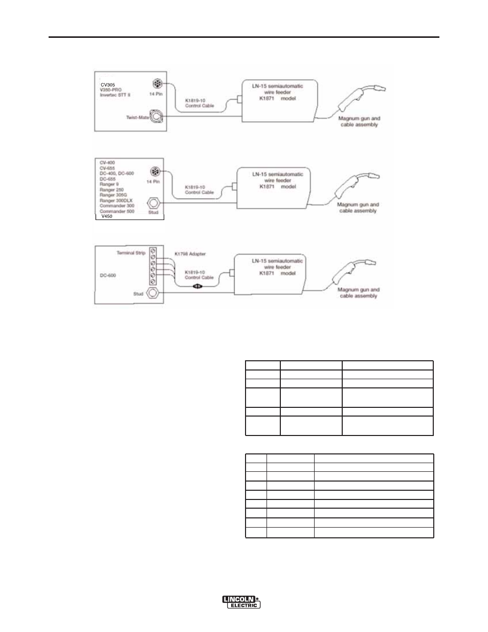
CONNECTION DIAGRAM, CONTROL
CABLE MODELS
( See Figure A.1)
CONTROL CABLE CONNECTIONS
For Control Cable model, attach the control cable from
the LN-15 to power source. Do not use more than 150
ft (45 m) of cable.
Table A.2 Trigger Connector J1 (5 Pin)
PIN
Lead #
Function
A
556
Trigger
B
-
Not used
C
554
Trigger/ 83%
Procedure ground
D
555
83% Procedure
E
554
Trigger/ 83%
Procedure ground
Table A.3 Control Cable Receptacle (8 Pin
PIN
Lead #
Function
A
41
42 VAC
B
42
42 VAC
C
2
Output Control (trigger)
D
4
Output Control (trigger)
E
21
Work Sense Lead
F
75
Remote Voltage Control
G
76
Remote Voltage Control
H
77
Remote Voltage Control
-3
-3
-3
FIGURE A.1