Installation, Warning – Lincoln Electric IM847 LF-72 WIRE FEEDER User Manual
Page 19
A-11
INSTALLATION
LF-72
A-11
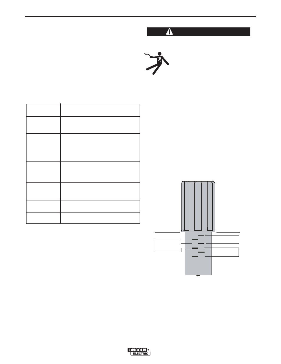
PRESSURE ARM ADJUSTMENT
ELECTRIC SHOCK can kill.
• Turn the input power OFF at the
welding power source before instal-
lation or changing drive rolls and/or
guides.
• Do not touch electrically live parts.
• When inching with the gun trigger, electrode
and drive mechanism are "hot" to work and
ground and could remain energized several sec-
onds after the gun trigger is released.
• Only qualified personnel should perform mainte-
nance work.
------------------------------------------------------------------------
The pressure arm controls the amount of force the
drive rolls exert on the wire. Proper adjustment of the
pressure arm gives the best welding performance.
Set the pressure arm as follows (See Figure A.6):
Aluminum wires
between 1 and 3
Cored wires
between 3 and 4
Steel, Stainless wires
between 4 and 6
FIGURE A.6
WARNING
ALUMINUM
OUTERSHIELD
METALSHIELD
INNERS HIELD
STEEL
STAINLE SS
CORED WIRES
SOLID WIRES
6
1
3
2
5
4
Gun Receiver
For use With
Bushing
K1500-1
K466-1 Lincoln gun connectors;
Innershield and Subarc guns)
K1500-2
K466-2, K466-10 Lincoln gun
connectors; Magnum 200/300/400
guns and compatible with Tweco®
#4)
K1500-3
K1637-7 Lincoln gun connectors;
Magnum 550 guns and compatible
with Tweco® #5)
K1500-4
K466-3 Lincoln gun connectors;
compatible with Miller® guns.)
K1500-5
(Compatible with Oxo® guns.)
K489-7
( Lincoln Fast-Mate guns.)
7. Disconnect the shielding gas hose from the gun
bushing, if required.
8. Connect the shielding gas hose to the new gun
bushing, if required.
9. Rotate the gun bushing until the thumb screw hole
aligns with the thumb screw hole in the feed plate.
Slide the gun receiver bushing into the wire drive
and verify the thumb screw holes are aligned.
10. Tighten the socket head cap screw.
11. Insert the welding gun into the gun bushing and
tighten the thumb screw.