0 ups monitoring, 4 computer interface port, Æän% zmp – APC 600 User Manual
Page 28
26
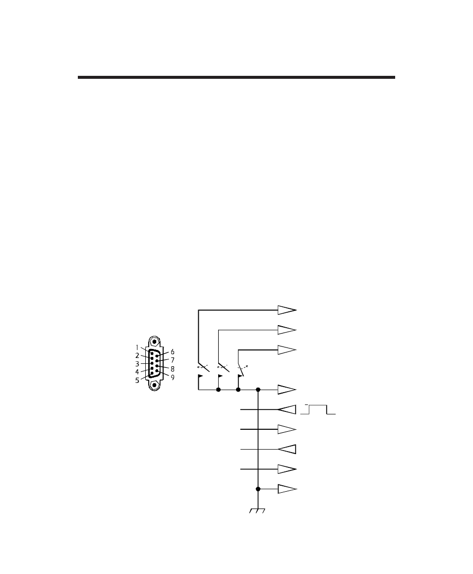
6.4 Computer interface port
The computer interface port is diagramed below. Those with technical
abilities wishing to use this port in a special application should be aware of
the following limitations and capabilities of the interface.
■ Outputs at Pins 3, 5, and 6 are open-collector outputs which must be
pulled up to a common referenced supply no greater than +40 Vdc. The
transistors are capable of a maximum noninductive load of 25 mAdc. Use
only Pin 4 as the common.
■ The output at Pin 2 generates a low-to-high RS-232 level when the output
load transfers to UPS battery power. The pin is normally at a low RS-232 level.
■ When on-battery, the UPS shuts down (after a delay) when a high RS-232
level is applied to Pin 1 for 4.5 seconds.
■ An unregulated +24 Vdc appears at Pin 8 of the interface port whenever
the UPS is powered. The supply is limited to 40 mAdc maximum.
■ Applying a momentary (approx. 1 sec.) high RS-232 level to Pin 7 turns
the UPS on. A momentary low RS-232 level turns the UPS off. Pin 7 should
be normally unconnected.
6.0 UPS Monitoring
n
s
¢
T
Q
%¤ Æp§m $%¢¢ mz¤ p
%h4 pap $%¢¢ Æ44 $¨ m
mp É4d $%¢¢ ¤z¤ p
%h4 pap $%¢¢ Æ44 &¨ ¤
Å4
Åphhpm
ph4dd© Ådppa
mp É4d %m4d
ph4dd© zpm
p§ Ä4p© %m4d
ph4dd© zpm
mp É4d %m4d
TQ
G
("% &¤mpm&¤mpyy mz¤
(mp¤d4pa
¢ )aR ¤z¤
ÆÄn% zmp¤