Installation, Reconnect procedure, Caution – Lincoln Electric IM602 IDEALARC DC-655 User Manual
Page 13: Warning, A-4 input power supply connections, Dc-655
A-4
INSTALLATION
DC-655
A-4
INPUT POWER SUPPLY CONNECTIONS
A qualified electrician should connect the input power
supply leads.
1.
Follow all national and local electrical codes.
2.
Use a three-phase line.
3.
Remove the input access door at upper rear of the
machine.
4.
Follow input supply connection diagram located
on the inside the door. For multiple voltage
machines, follow the diagram for the voltage that
is within 10% of your actual input line voltage.
5.
Connect the three-phase AC power supply leads
L1, L2, and L3 to the input contactor
terminals in the input box assembly. See Figure
A.1.
RECONNECT PROCEDURE
Electric Shock Can Kill
• Disconnect input power before perform-
ing this procedure.
------------------------------------------------------------------------
Multiple voltage machines are shipped connected to
the highest input voltage listed on the machineʼs rating
plate. Before installing the machine, check that the
reconnect panel in the input box assembly is connect-
ed for the proper voltage.
Failure to follow these instructions can cause immedi-
ate failure of components within the machine. When
powering welder from a generator be sure to turn off
welder first, before generator is shut down in order to
prevent damage to welder.
------------------------------------------------------------------------
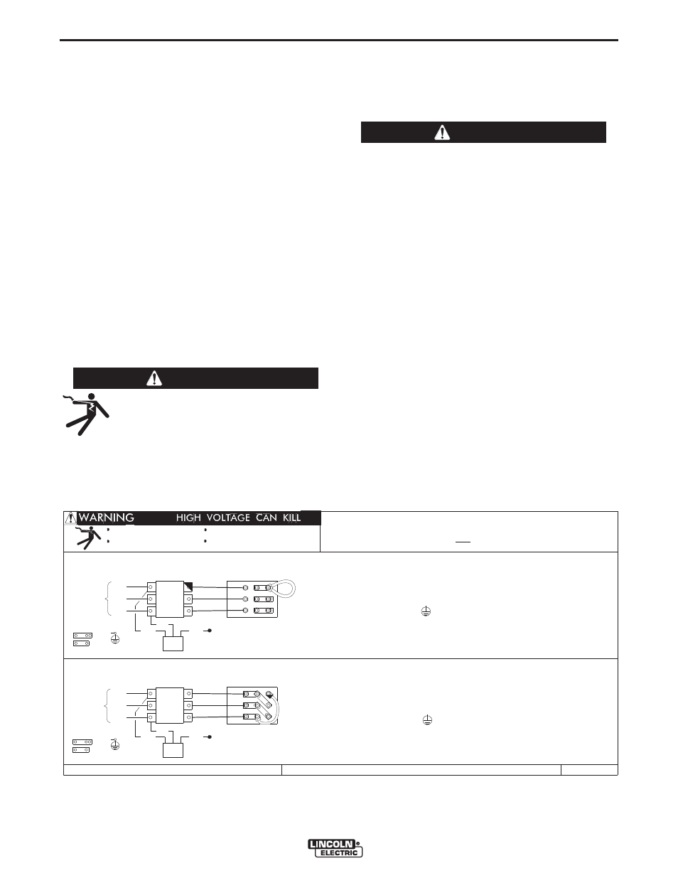
To reconnect a multiple voltage machine to a different
voltage, remove input power and refer to the input
connection diagram located on the inside of case back
input access door. Follow the diagram for the voltage
that is within 10% of your actual input line voltage.
1.
Figure A.2 shows a sample of the reconnect
instructions for a dual voltage machine.
CAUTION
1. TURN OFF THE INPUT POWER USING THE DISCONNECT SWITCH AT THE FUSE BOX.
H2
GND
5. MOUNT THE LINKS IN THE POSITIONS SHOWN. CONNECT THE FLEX LEAD AS SHOWN;
LEADS TO THE INPUT SIDE OF CR1 CONTACTOR AS SHOWN.
L1
LINES
4. CONNECT TERMINAL MARKED TO GROUND PER LOCAL AND NATIONAL ELECTRIC
2. DISCONNECT AND INSULATE THE H3 LEAD TERMINAL WITH TAPE TO PROVIDE AT
LEAST 600 VOLT INSULATION.
CODES.
INSTALL AND TIGHTEN ALL OF THE HEX NUTS.
POSITIONING THE LUGS TO MAINTAIN MAXIMUM CLEARANCE TO THE LINKS.
D-UF
INPUT
3. CONNECT L1, L2 & L3 INPUT SUPPLY LINES AND H1 & H2 CONTROL TRANSFORMER
W CR1
V
L3
U
H3
CONTACTOR
L2
L1
W
V
GND
CR1
L3
L2
1. TURN OFF THE INPUT POWER USING THE DISCONNECT SWITCH AT THE FUSE BOX.
2. DISCONNECT AND INSULATE THE H2 LEAD TERMINAL WITH TAPE TO PROVIDE AT
LEAST 600 VOLT INSULATION.
ALL OF THE HEX NUTS.
4. CONNECT TERMINAL MARKED TO GROUND PER LOCAL AND NATIONAL ELECTRIC
CODES.
5. MOUNT THE LINKS IN THE POSITIONS SHOWN; DOUBLE OR TRIPLE STACK THE LINKS
IN THREE POSITIONS. LOOP THE FLEX LEAD IN THE POSITION SHOWN; POSITIONING
THE LUGS TO MAINTAIN MAXIMUM CLEARANCE TO THE LINKS. INSTALL AND TIGHTEN
DUAL VOLTAGE MACHINE
INPUT SUPPLY CONNECTION DIAGRAM
IMPORTANT: CHANGE LINK POSITIONS AND CONTROL TRANSFORMER CONNECTIONS.
NOTE: MACHINES ARE SHIPPED FROM FACTORY CONNECTED FOR OVER 300 VOLTS
Do not touch electrically live parts
Only qualified persons should install,
use or service this equipment
Do not operate with covers
removed
Disconnect input power before
LEADS TO THE INPUT SIDE OF CR1 CONTACTOR AS SHOWN.
TRANSF.
CONTROL
TRANSF.
CONTROL
3. CONNECT L1, L2 & L3 INPUT SUPPLY LINES AND H1 & H3 CONTROL TRANSFORMER
CONNECTION FOR HIGHEST RATING PLATE VOLTAGE
servicing
M18225
INPUT
CONTACTOR
CONNECTION FOR LOWEST RATING PLATE VOLTAGE
H2
H1
LINKS
LINES
THE LINCOLN ELECTRIC CO., CLEVELAND OHIO U.S.A.
LINKS
U
H1
H3
WARNING
FIGURE A.2 Dual Voltage Machine Reconnection Procedure