Installation instructions (2-roll feeders), Warning – Lincoln Electric IM638 Clutched Aluminum Drive Roll Kits K1682 User Manual
Page 3
KP1682 CLUTCHED ALUMINUM DRIVE ROLL KITS
3
INSTALLATION INSTRUCTIONS
(2-ROLL FEEDERS)
1. Turn off input power to the welding power source
using the disconnect switch at the fuse box before
installing the clutch drive system.
2. Remove the gun and cable, drive roll, and guide
tubes from the feeder.
3. Remove the hex head screw, clamping collar, and
key from the drive shaft. Save these parts as they
will be required if this feeder is used for normal
operation.
4. Clean and polish the feeder’s drive shaft using a
fine abrasive cloth (400 grit). The drive roll must be
able to spin freely.
5. Remove the pressure arm by removing the hex
head bolt from the gearbox. The bolt, pivot tube,
and thin spacer will be required for the new tension
arm. Remove these parts from the original tension
arm. (See Figure 1).
Figure 1
6. Remove the idle roll arm assembly by removing the
retainer. Store for possible reuse. (See Figure 2).
Figure 2
Note: All the parts that were removed from the feeder
should be saved. These parts are required for
normal operation. Now the system is ready to
install all parts of the clutched drive roll system.
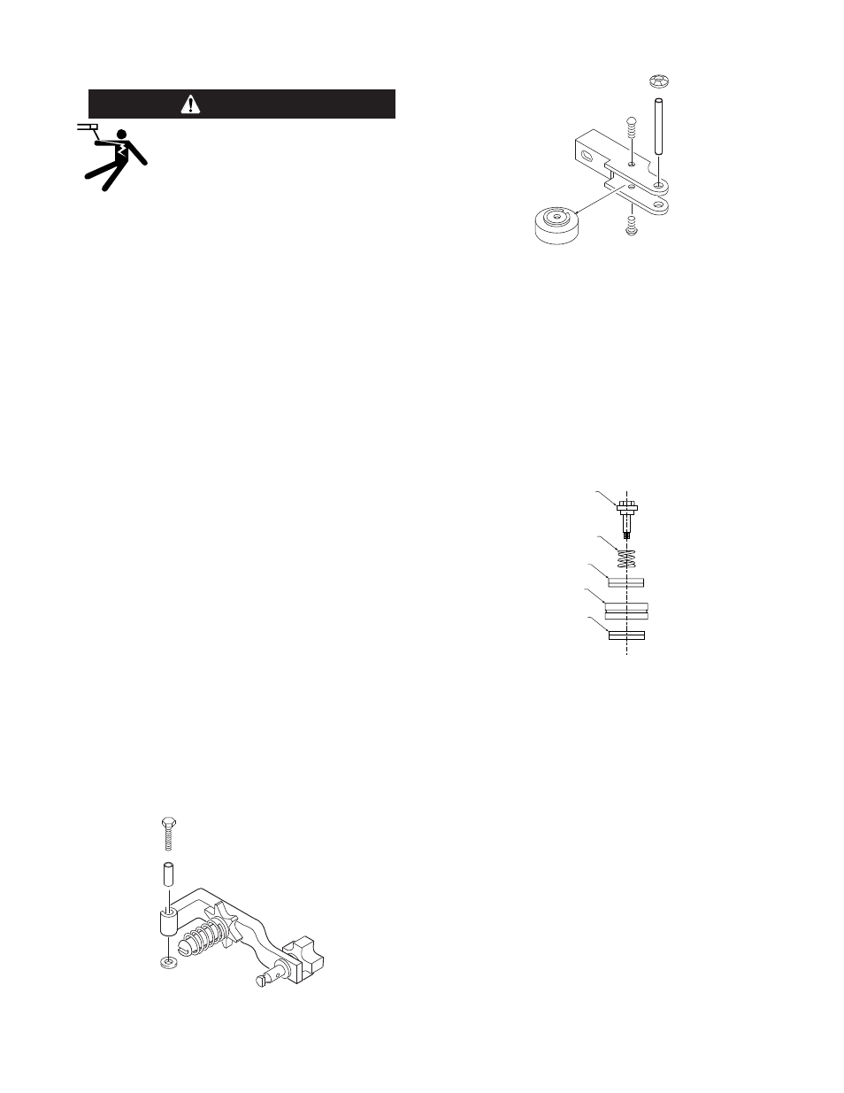
7. As shown in Figure 3, install the bottom clutch pad,
the drive roll, the top clutch pad, and the spring &
bolt to the feeder’s drive shaft. DO NOT OVER-
TIGHTEN THE BOLT. Only snug it to secure the
assembly. The proper tension is preset for the wire
size and does not need adjustment. Make sure that
the clutch material faces the drive roll.
Figure 3
8. Install the short incoming guide tube and outgoing
guide tube into their respective locations. Do not
overtighten the thumb screws as they may damage
the guide tubes.
9. Install the new idle roll assembly on the hinge pin.
A retainer can be used but is not necessary.
10. Assemble the new quick release pressure arm to
the gearbox using the bolt, pivot tube, and washer
removed in Step 5. The idle roll tension is preset
for optimum feeding of aluminum wires. No
adjustment is necessary.
11. Install a new Magnum gun and cable with a fresh
liner designed specifically for aluminum. Page 5
contains recommended liners and tips for stan-
dard Magnum guns.
12. Be certain that the guide tubes do not touch the
drive roll or idle roll. If they do touch, readjust
them and tighten in place.
ELECTRIC SHOCK Can Kill
• Only qualified persons should perform
this installation.
• When inching the electrode, the drive mechanism
and the electrode may be electrically "hot".
• The electrode cable that feeds the LN-25 may be
electrically "hot" even when the system is not being
used. Be sure to turn off the welding power source
before changing drive rolls or guides.
• Cabinet feeders like the LN-25 are recommended to
protect the wire from airborne dust. Dirt that accumu-
lates on the wire can be forced into the feeder and
welding gun creating feeding resistance. Maintaining
a clean feeder and a clean wire supply will minimize
feeding problems.
------------------------------------------------------------------------
WARNING
yyy
yyy
Bolt
Drive Roll
Top
Clutch
Pad
Bottom
Clutch
Pad
Spring