Installation – Lincoln Electric IM743 INVERTEC V350-PIPE User Manual
Page 10
A-3
INSTALLATION
A-3
V350-PIPE
LN-7 Connection Instructions
•
Turn the Invertec power switch "off".
•
Connect the K480 control cable from the LN-7 to the
115VAC 14-pin wire feeder MS-style connector on the
rear of the Invertec.
•
Connect the electrode cable to the output terminal of
the polarity required by electrode. Connect the work
lead to the other terminal.
•
Set the meter polarity switch on the front of the Invertec
to coincide with wire feeder polarity used. The wire
feeder will now display the welding voltage.
•
If K480 is not available, see connection diagram
S19404 for modification of K291 or K404 LN-7 input
cable with K867 Universal Adapter Plug.
•
If a remote control such as K857 is to be used with the
LN-7, the remote can be connected directly to the 6-pin
MS-style connector on the front of the Invertec or use a
K864 adapter to connect the LN-7 and the remote to
the 115VAC 14-pin MS-style connector on the rear of
the Invertec. (See connection diagram S19901)
LN-10 Connection Instructions
•
Turn the Invertec power switch "off"
•
Connect the K1505 control cable from the LN-10 to the
Invertec 24/42VAC 14-pin MS-style connector on the
rear of the Invertec.
•
Connect the electrode cable to the output terminal of
polarity required by the electrode. Connect the work
lead to the other terminal.
•
Set the meter polarity switch on the front of the Invertec
to coincide with wire feeder polarity used.
•
See the LN-10 manual for details on accessing Control
DIP Switch
LN-742 Connection Instructions
•
Turn the Invertec power switch "off"
•
Either a K591 or a K593 Input cable assembly is
required to connect the LN-742 to the Invertec.
•
Connect the control cable from the LN-742 to the
24/42 VAC 14-pin wire feeder MS-style connector
on the rear of the Invertec.
•
Connect the electrode cable to the output terminal
of the polarity required by electrode. Connect the
work lead to the other terminal.
•
Set the meter polarity switch on the front of the
Invertec to coincide with wire feeder polarity used.
The wire feeder will now display the welding volt-
age.
•
If a remote control such as K857 is to be used with the
LN-742, the remote can be connected directly to the 6-
pin MS-style connector on the front of the Invertec or use
a K864 adapter to connect the LN-742 and the remote to
the 24/42VAC 14-pin wire feeder MS-style connector on
the rear of the Invertec.
Cobramatic Connection Instructions
•
Turn the Invertec power switch "off"
•
Connect the control cable from the Cobramatic to
the 24/42 VAC 14-pin wire feeder MS-style con-
nector on the rear of the Invertec.
•
Connect the electrode cable to the output terminal
of the polarity required by electrode. Connect the
work lead to the other terminal.
•
Set the meter polarity switch on the front of the
Invertec to coincide with wire feeder polarity used.
•
If a remote control such as K857 is to be used with
the Cobramatic, the remote can be connected
directly to the 6-pin MS-style connector on the front
of the Invertec or use a K864 adapter to connect
the cobramatic and the remote to the 24/42VAC
14-pin wire feeder MS-style connector on the rear
of the Invertec.
LN-23P Connection Instructions
1. Shut the welder off.
2. Connect the LN-23P as per instructions on the
appropriate connection diagram in Section F.
(NOTE): When connecting an LN-23P to the
Invertec.
3. Set the "VOLTMETER" switch to "-".
4. Set the "MODE" switch to "CV WIRE" position.
5.
Set the "WELD TERMINALS" switch to
"REMOTELY CONTROLLED".
6. Set the "ARC CONTROL" knob to "0" initially and
adjust to suit.
General Instructions for Connection of Wire
Feeders to V350-PIPE
Wire feeders other than those listed above may be
used provided that the auxiliary power supply rating of
the V350-PIPE is not exceeded. K867 universal
adapter plug is required. See connection diagram
S24985 on page F-4.
REMOTE CONTROL OF INVERTEC
Remote Control K857, Hand Amptrol K963 and Foot
Amptrol K870.
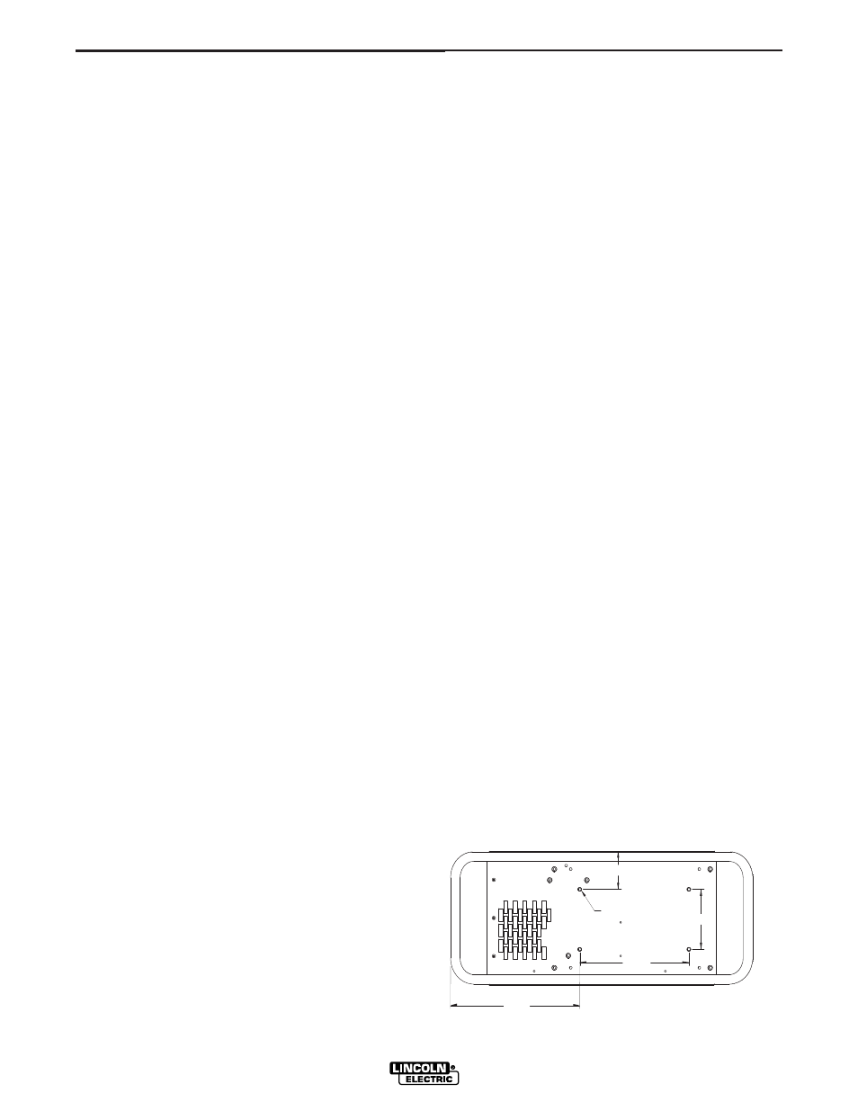
UNDERCARRIAGE MOUNTINGS
5.50
10.00
MOUNTING HOLE LOCATIONS
M19527
1/4-20 NUT (4 PLACES)
NOTE: MOUNTING SCREWS CA
8/00
N NOT PROTRUDE MORE THAN
0.5 INCHES INSIDE THE MACHINE.
11.84
3.50