Installation, Output connections, Electric shock can kill – Lincoln Electric IM609 SQUARE WAVE TIG 275 User Manual
Page 14: Work cable connection, Warning
A-7
INSTALLATION
SQUARE WAVE TIG 275
A-7
Designations on the reconnect panel LOW, MID, and
HIGH correspond to the nameplated input voltages of
a triple voltage welder. Dual voltage welders use only
LOW and HIGH.
EXAMPLE: On a 208/230/460 volt welder, LOW is
208V, MID is 230V, and HIGH is 460V.
3. Make sure all connections are tight. Replace the
case side and all screws.
OUTPUT CONNECTIONS
To avoid being startled by a high frequency shock,
keep the TIG torch and cables in good condition.
------------------------------------------------------------------------
ELECTRIC SHOCK can kill.
• Turn the power switch of the power
source “OFF” before installing adapters
on cable or when connecting or discon-
necting adapter plugs to power source.
----------------------------------------------------------------------------
See Figure B.1 for the location of the work and elec-
trode terminals, the gas and optional water solenoids,
and the Remote Receptacle.The Square Wave TIG
275 is equipped with Twist-Mate connectors for the
electrode and work connection.
WORK CABLE CONNECTION
The Twist-Mate connection allows fast and reliable
work cable attachment to the work terminal of the
Square Wave TIG 275 welding power supply.
Assemble the work cable by attaching the correct
Twist-Mate adapter and work clamp to an adequately-
sized welding cable. The Twist-Mate cable plug includ-
ed with the machine is designed to accept a welding
cable size of of #2 to #1. See Table A.1 and A.2 for rec-
ommended sizes and corresponding hardware.
Assemble the correct Twist-Mate-adapter plug to the
work cable as follows:
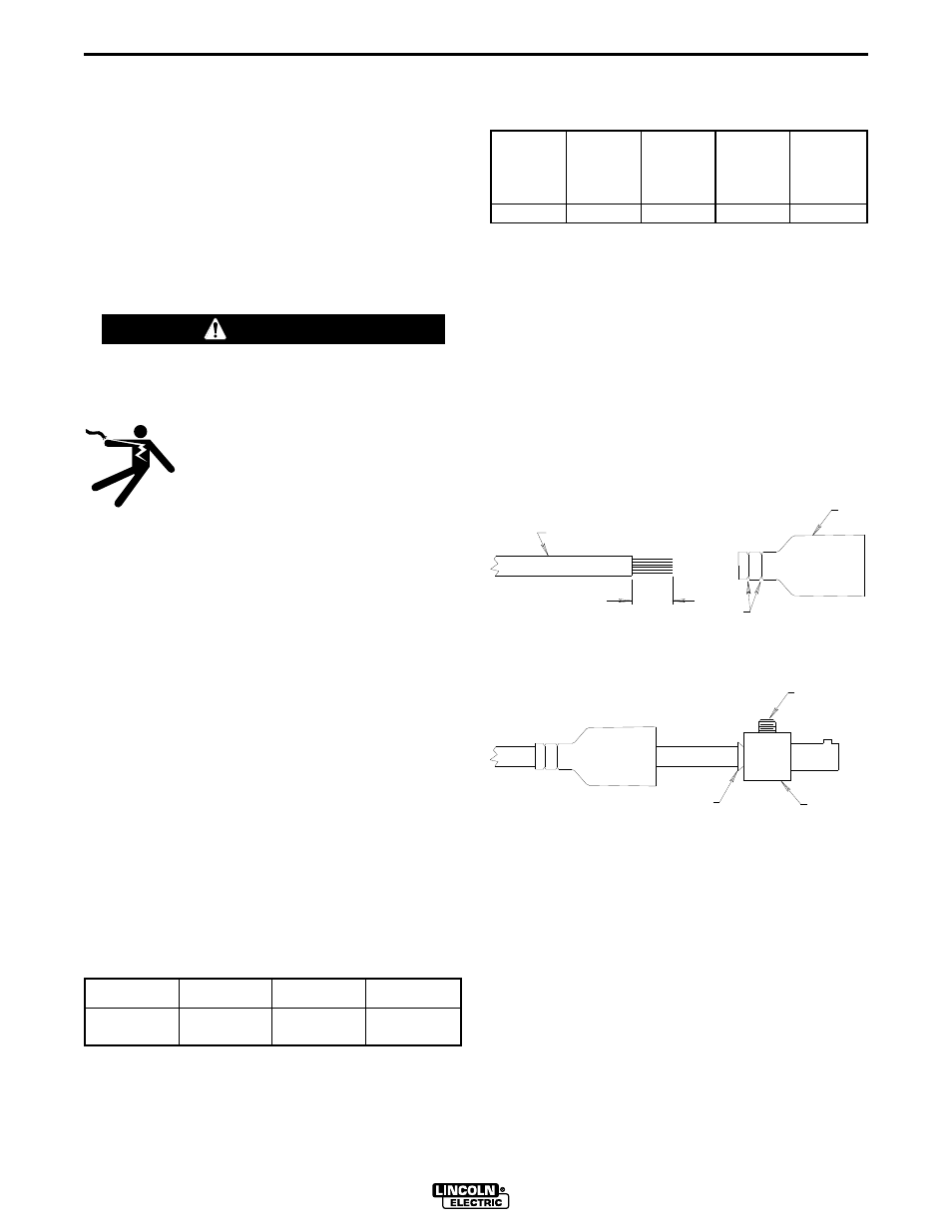
1. Skin the cable jacket to 1.00 in (25.4 mm) for a #2
thru 2/0 (35 thru 70 mm2) cable. Skin the cable
jacket to 1.50 in (38.1 mm) for a 2/0 thru 3/0 (70 thru
95 mm2) cable.
2. If necessary, trim the cable end of the rubber boot
to match the diameter of the cable.
3. Slide the rubber boot onto the skinned cable end.
Use soap for lubricant if required.
4. Slide the copper tube into the brass plug. Insert
skinned cable into the copper tube.
5. Tighten set screw(s) to collapse copper tube.
Screw(s) must apply firm pressure against welding
cable.
6. Slide the rubber boot over the brass plug. The rub-
ber boot must be positioned to completely cover all
electrical surfaces after the plug is locked into the
receptacle. For more details see S18737PRINT or
instructions included with the adapter kit.
WARNING
TABLE A.1
Cable Sizes for Combined Lengths of Copper
Electrode and Work Cable
Machine Size
Lengths up to
100 ft
100 to 200 ft
200 to 250 ft
275 Amp
40% Duty Cycle
#1 (42.4mm2)
1/0 (53.5mm2)
2/0 (67.4mm2)
TABLE A.2
Recommended Work and Stick Electrode
Components
Twist Mate
Cable Plug
for Work
Lead
(#2 to #1)
Twist Mate
Cable Plug
for Work
Lead
(1/0 to 2/0)
Twist Mate
Cable Plug
for Work
Lead
(2/0 to 3/0)
Work
Clamp
Electrode
Holder
K852-50
K852-70
K852-95
K910-1
K909-4
SEE
WELDING CABLE
TRIM
ABOVE
BOOT
COPPER TUBE
SET SCREW
(70-95 SIZE MAY
HAVE 2 SET
BRASS PLUG
SCREWS)