Johnson Level & Tool Mfg. 40-6550 User Manual
Page 14
14
©2005 Johnson Level & Tool
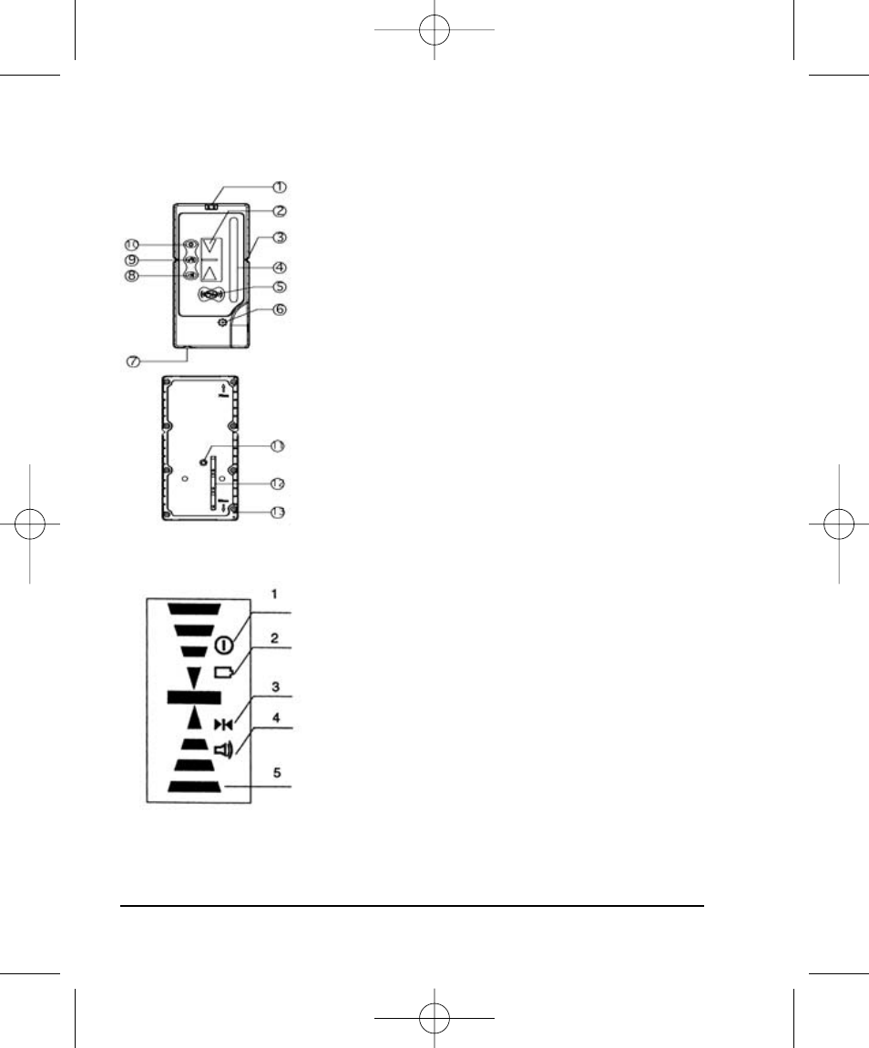
3. Components
(a) Structure
1) Horizontal vial
2) Right-faced display window
3) Lineation slot
4) Receiving window
5) Power button
6) Buzzer
7) Battery-box
8) Sound switch
9) Coarse/Fine detection switch
10) Illumination switch
11) Mounting hole
12) Battery installation symbol
13) Scale
(b) Display
1. Power indicator
2. Low battery indicator
3. Detection indicator
4. Sound indicator
5. Detected position (grade) indicator
40-6540_6550 English 6/28/05 9:44 AM Page 14
This manual is related to the following products:
See also other documents in the category Johnson Level & Tool Mfg. Tools:
- 1750-1000 (2 pages)
- 40-6900 (16 pages)
- 40-6926 (12 pages)
- 40-6926 (12 pages)
- 40-6910 (16 pages)
- 40-6936 (38 pages)
- 40-6250 (12 pages)
- 40-6065 (16 pages)
- 1455-0000 (42 pages)
- 1457-1000 (12 pages)
- 40-6060 (12 pages)
- 1880-2400 (12 pages)
- 40-6028 (12 pages)
- 40-6500 (24 pages)
- 40-6080 (16 pages)
- 40-6515 (84 pages)
- 40-6527 (24 pages)
- 40-6580 (30 pages)
- 40-6529 (30 pages)
- 40-6530 (21 pages)
- 40-6502 (22 pages)
- 40-6537 (18 pages)
- 40-6525 (21 pages)
- 40-6522 (26 pages)
- 40-6535 (20 pages)
- 40-0917 (8 pages)
- 40-0922 (14 pages)
- 40-6064 (2 pages)
- 40-6932 (36 pages)
- 40-6004 (24 pages)
- 40-6001 (32 pages)
- 40-6430 (2 pages)
- RAS-1 (67 pages)
- 40-6620 (16 pages)
- 40-6640 (20 pages)
- 40-6662 (20 pages)
- GL100 MX (3 pages)
- L100M MX (4 pages)
- 40-6602 (18 pages)
- 40-6230 (1 page)
- 40-6616 (12 pages)
- 40-6210 (5 pages)
- 40-6200 (5 pages)
- 9100 (3 pages)