Introduction, Specifications, Inspection of pump – Davey ISOSPEC CM Series ISO2858 Heavy Duty Industrial Centrifugal Pump User Manual
Page 2: Delivery, Storage, Installation location, Foundations, Suction piping, Discharge piping
~ 2 ~
Introduction
Thank you for purchasing a quality Davey product. It is
our commitment to satisfy our customers by offering our
very best service.
This manual contains instruction for installation,
operation and maintenance of ISOspec
®
CM series
of single stage, non-self priming, centrifugal pumps.
Therefore, please read it carefully before use to obtain a
long satisfying service life of the purchased unit.
Davey ISOspec
®
CM series centrifugal pumps are
designed with high efficiency and low maintenance
features.
Specifications
Model designation (example) :-
CM 125×100-200
Nominal dia. of impeller (mm)
Dia. of outlet (mm)
Dia. of inlet (mm)
Series code of pump
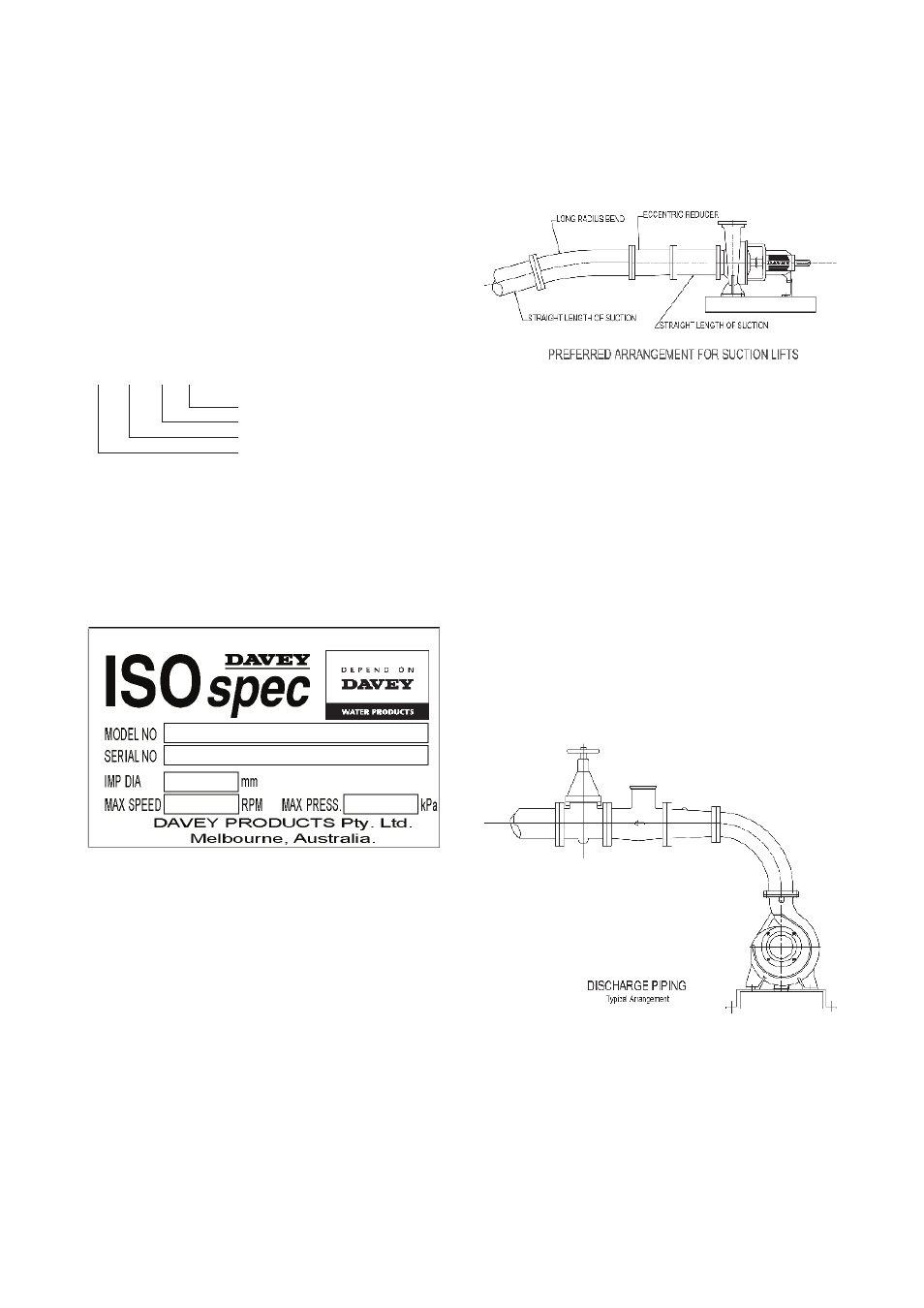
Inspection of Pump
Always check on receipt of delivery you have
received the correct pump unit. To identify, see above
specifications and label below. Check correct motor kW
& speed on motor nameplate (attached to motor) prior to
installation.
Delivery
Upon receipt the unit should be thoroughly inspected for
any damage sustained during transit. Any equipment
damage or shortfall should be immediately advised to
your nearest Davey office or Davey customer service
centre.
Storage
If the unit is not to be installed immediately, it should be
stored in a clean, dry and preferably warm environment.
Shafts of stored motors should be rotated occasionally.
Specific vibration during storage may lead to “brinelling”
of the bearings, therefore motors that are subject to
extended storage where vibration exists, should be fitted
with bearing locks.
Installation Location
It is important to select a site as close to the liquid
source as possible. When a suction lift is unavoidable,
install the pump as near to the water level as possible
(see suction piping). You should always check
the maximum permissible lift of the pump from its
performance curve.
Foundations
The pump unit should be mounted on a foundation that
is substantial enough to withstand the weight of the unit
& large enough to accommodate all mounting feet so
they can be securely fixed to avoid movement.
Suction Piping
All fittings & suction piping should be free of air leaks.
When a suction lift or long suction lengths are
unavoidable, consideration should be given to over
sizing the suction line to reduce suction losses.
On suction lifts a foot valve will be required, sized equal
to the suction line size. For applications on creek beds
or dams, please install a foot valve & strainer, well
submerged below the surface, to reduce whirlpools & air
inclusion. Air inclusion can result in cavitation reducing
the pump performance & eventually destroying the pump
or its components.
If bends are required, long radius bends should be used.
To help ensure a less turbulent entry into the pump,
a straight length of pipe should be installed between
any bends and the pump inlet. This straight length
should be at least 2.5 times the pump inlet diameter in
length. Pipework supports should be installed to both
inlet and outlet pipes to ensure that they are supported
independently of the pump flanges.
Discharge Piping
Discharge piping must be selected of a size that would
equal the discharge of the pump. For long discharge
lengths, consideration should be given to using larger
diameter pipework. Larger size pipes have lower
pressure losses for a given flow rate, and may help
reduce the running costs for your pumping system.
Talk to your nearest Davey dealer to calculate all system
losses. To avoid air pockets in discharge lines at high
points, vent cocks may be required to release air blocks
accumulated within the system. Air pockets may affect
the performance of the pump. A throttling valve should
be installed in the discharge line to ensure the pump
works within the performance curve.