Minimum flow requirements – Davey 6 Submersible Borehole Pumps User Manual
Page 5
5
5.4
Lowering the pump
It is recommended to check the well by means of an
inside calliper before lowering the pump to ensure
unobstructed passage. Lower the pump carefully into
the well, taking care not to damage the motor cable.
NOTE: Do not lower or lift the pump by means of
the motor cable.
Fig. 5.4
5.5
Installation Depth
The dynamic water level should always be above the
suction motor adaptor of the pump. The minimum
safety margin should be 1 metre head at the bores
lowest water level. When the pump has been installed
to the required depth, the installation should be
finished by means of a well seal. Slacken the straining
wire so that it becomes unloaded and lock it to the
well seal by means of wire locks.
6. Start-Up
When the pump has been connected correctly and it
is submerged in the liquid to be pumped, it should be
started with the gate valve closed off to approx. 1/3
of its maximum volume of water. Check the direction
of rotation as described in section 4.2 Checking of
Direction of Rotation. If there are impurities in the
water, the valve should be opened gradually as
the water becomes clearer. The pump should not
be stopped until the water is completely clean, as
otherwise the pump parts and the non-return valve
may choke up. As the valve is being opened, the
drawdown of the water level should be checked to
ensure that the pump always remains submerged.
The dynamic water level should always be above the
suction motor adaptor of the pump, see section 3.1
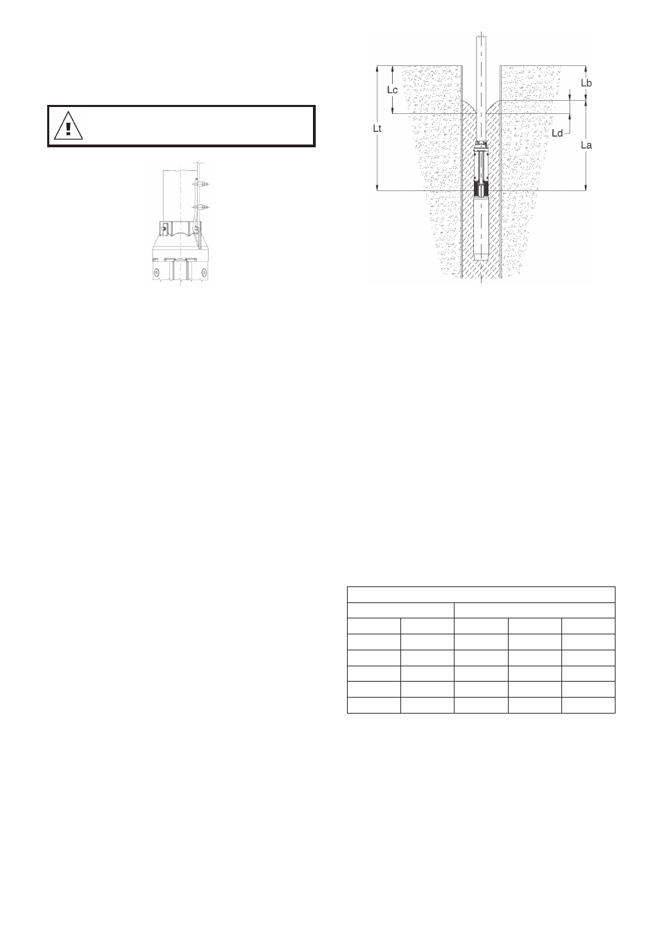
Positional Requirements and fig. 6.
Fig. 6
La: Minimum installation depth.
(suggested: minimum 1 mt)
Lb: Static water level.
Lc: Dynamic water level.
Ld: Difference between static and dynamic level.
Lt: Installation depth.
If the pump can pump more than yielded by the well,
it is recommended to fit a control unit of dry-running
protection.
If no water level electrodes or level switches are
installed, the water level may be drawn down to the
suction motor adaptor of the pump and the pump will
then draw in air.
Long time operation with water containing air may
damage the pump and cause insufficient cooling of
the motor.
7. Minimum Flow Requirements
6” Motors
Bore size
Minimum Flow Rate
Inch
mm
lpm
gpm
m3/hr
8
203.2
170
37.4
10.2
10
254
340
74.9
20.4
12
304.8
530
116.7
31.8
14
355.6
760
167.4
45.6
16
406.4
1060
235
63.6
If flow rate is less than above or water is coming from
above the pump a shroud must be fitted. A shroud is
always required in an open body of water eg. a dam
or river, or a cascading bore.