Electrical connection, Pump installation – Davey 6 Submersible Borehole Pumps User Manual
Page 4
4
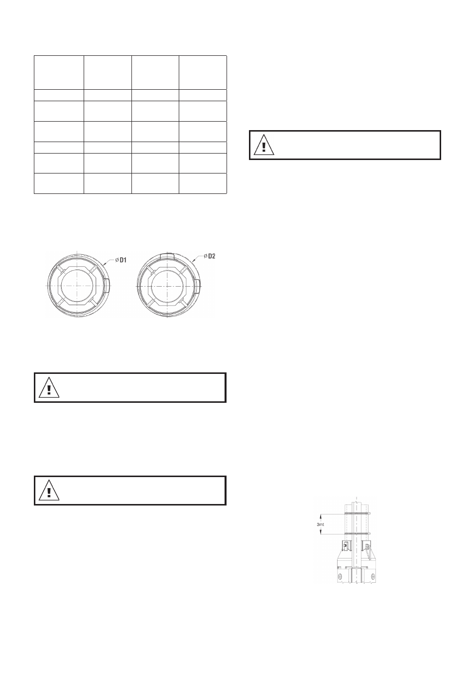
3.2
Diameter of Pump/Motor
The maximum diameter of the pump and of the pump
with motor is as shown in the table below:
Diameter
with 1
cable cover
Diameter
with 2
cable covers
External
Motor
Diameter
Pump 6”
141
145
-
Pump 6”
with motor 4”
141
-
95.25
Pump 6”
with motor 6”
144
146.5
136.5
Pump 8”
186.5
192
-
Pump 8”
with motor 6”
186.5
192
136.5
Pump 8”
with motor 8”
195
197.5
187.5
Verify the borehole with an inside calliper to ensure
unobstructed passage.
With
With
Standard Motor
Star Delta Motor
It is recommended to check the borehole with an
inside calliper to ensure unobstructed passage.
4.
Electrical Connection
Before starting work on the pump, make sure that
the electricity supply has been switched off and
that it cannot be accidentally switched on.
4.1 General
The electrical connection should be carried out by
an authorised electrician in accordance with local
regulations. The supply voltage, rated maximum
current and cos appear from the loose data plate
that must be fitted close to the installation site.
The motor must be earthed and connected to an
external mains switch with suitable earth leakage
installed by a qualified electrician.
4.2
Checking of Direction of Rotation
When the pump has been connected to the electricity
supply, determine the correct direction of rotation as
follows.
Prior to installation, manually start the pump unit
for no longer than 2 seconds run time, then turn off.
The unit should be rotating counter clockwise when
looking down onto pump discharge.
If the pump has been installed, please refer to below
steps to determine rotation.
1. Start the pump and check the head developed with
gate the valve partially open.
2. Stop the pump and interchange two of the phase
connections.
3. Start the pump and repeat point 1. with gate valve
in the same position.
4. Stop the pump.
Compare the results taken under points 1. and 3. The
connection which gives the higher head is the correct
connection.
The Pump must not be started until the suction
motor adaptor has been completely submerged in
the liquid.
5. Pump Installation
Before starting any work on the pump/motor, make
sure that the electricity supply has been switched off
and that it cannot be accidentally switched on.
5.1
Assembly of Motor and Pump
Couple the pump and the motor properly along the
same axis and insert the motor shaft in the pump shaft
joint: the coupling must not be forced.
Tighten screws or nuts, screwing up pump-motor
flanges, diagonally with a 100Nm driving torque.
5.2
Riser Pipe
If a tool, e. g. a chain pipe wrench, is used when the
riser pipe is fitted to the pump, the pump must only be
gripped by the pump discharge chamber.
The threaded joints on the riser pipe must all be well
cut and fit together to ensure that they do not work
loose when subjected to torque reaction caused by
the starting and stopping of the pump.
The thread on the first section of the riser pipe which
is to be screwed into the pump should not be longer
than the threads in the pump.
After screwing the riser pipe into the pump inlet,
tighten the screw in the discharge outlet to prevent
loosening of the first section of the riser pipe.
5.3
Cable Fitting
Cable ties must be fitted every 3 metres to fix the
submersible drop cable and the straining wire, if
fitted, to the riser pipe of the pump. Cable fitting: Use
rubber/plastic cable ties. Once fastened, cut off the
remaining part of band.
Fig. 5
Where plastic pipes are used, some slackness must
be left between each cable tie as plastic pipes expand
when loaded. When flanged pipes are used, the cable
ties should be fitted above and below each joint.