3 data format table, Data format table, 1 _ x x x – Condec UPS3210 User Manual
Page 21: Where “x” can be any number
Operation
17
5. At this time, record the settings of switch S1. These settings must be changed in order to program the
serial output configuration.
6. After the data format and baud rate have been selected, refer to the “SERIAL OUTPUT
CONFIGURATION TABLE” in this section for the appropriate values for the M.S.D. “M” and the
L.S.D. “L.”
7. Set up switch S1 with the data derived from the “Serial Output Configuration Table”.
8. After switch S1 has been set, push the
ENTER
button on front panel to enter the data.
9. The selected values for “M” and “L” should now appear at location 64 in the correct order. If this is not
the case, go back and perform step “7” and try again.
10. To store this information permanently, close switch S3-2. The unit will display the following:
_ 1 _ X X X
where “X” can be any number
11. Push switch
S2
momentarily. As switch S2 is held down, the
XXX
on the display (see step “10”) becomes
377
. Release switch S2.
12. Return switch S1 to the original settings which had been recorded earlier in step “5”. Open switches on
switch S3 to resume normal operation.
2.11.3
DATA FORMAT TABLE
Format # 1
3 _ _ _ 0. 0 0 2 _
K
G
/
C
M
2 _ G
Format # 1 Data String
A)
P
RESSURE
R
ANGE
+ 1
SPACE
(
IF
POSITIVE
DATA
)
OR
"-"
IF
NEGATIVE
B)
D
ATA
* + 1
SPACE
.
C)
C
ONVERSION
+ 1
SPACE
.
D)
M
ODE
+
Format # 2
3 _ 0 0 0 . 0 0 2 _ G
Format # 2 Data String
A)
P
RESSURE
R
ANGE
+ 1
SPACE
(
IF
POSITIVE
DATA
)
OR
“-”
IF
NEGATIVE
B)
D
ATA
* + 1
SPACE
.
C)
M
ODE
+
ARRIAGE
R
ETURN
,
INE
F
EED
NOTE:
*
Data consists of seven characters including the decimal point. In format #1, leading zeros are located only one
character to the left of the decimal point. In format # 2, all unused characters will be leading zeros.
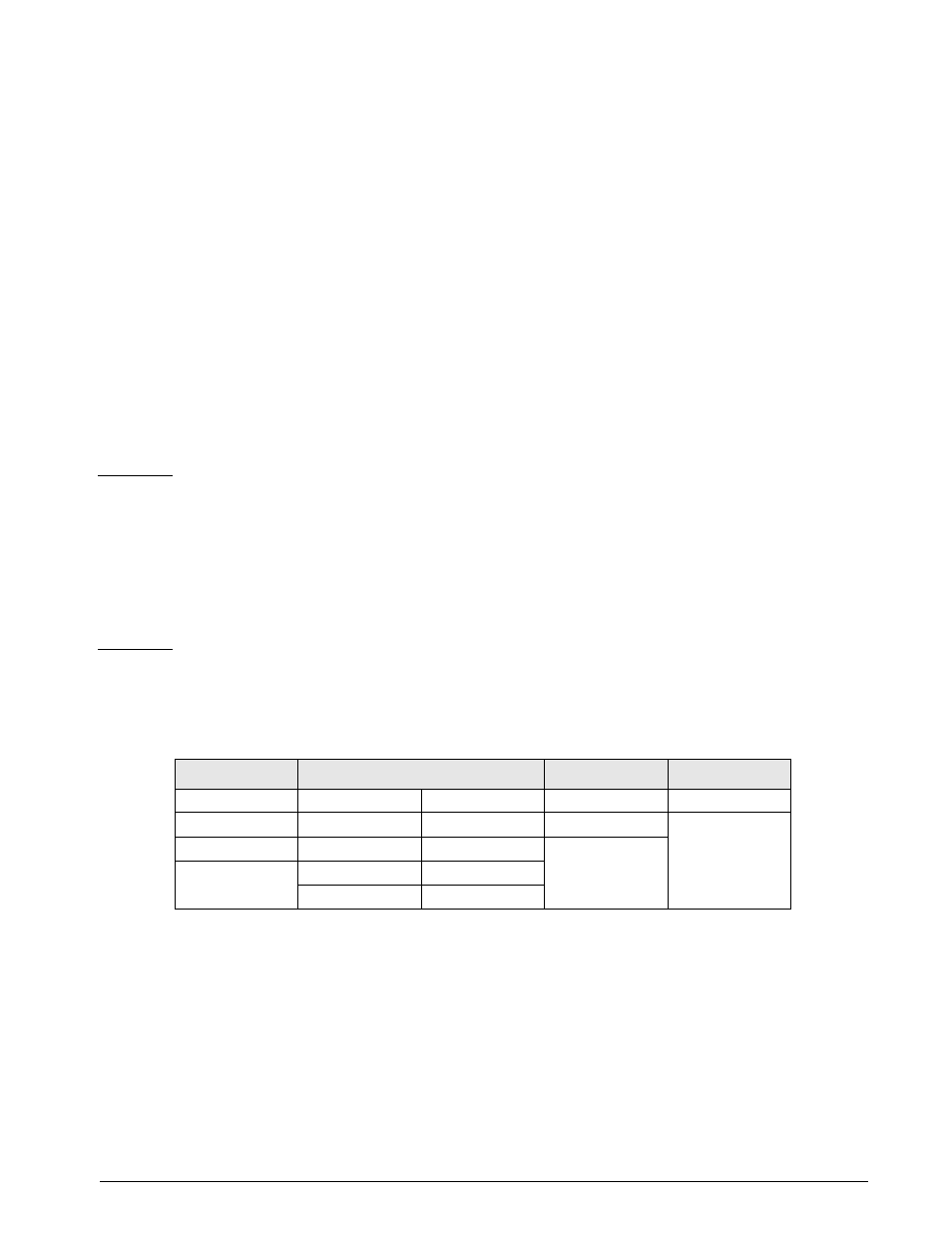
Conversion
Pressure Range
Mode
“O” Over Range
PSI
mBar
“1” High Range
“G” Gage
“U” Under Range
KPa
cm H
2
0
“2” Mid Range
“A” Absolute
“M” Motion
mm Hg
Kg/cm
2
“3” Low Range
“ D” Default
Bar
in H
2
O
in Hg
% F. S.
Table 2-7. Data Format Settings