3 rear panel configuration, Aution – Condec UPS3210 User Manual
Page 10
6
UPS3000/UPS3110/UPS3210 Operation & Maintenance Manual
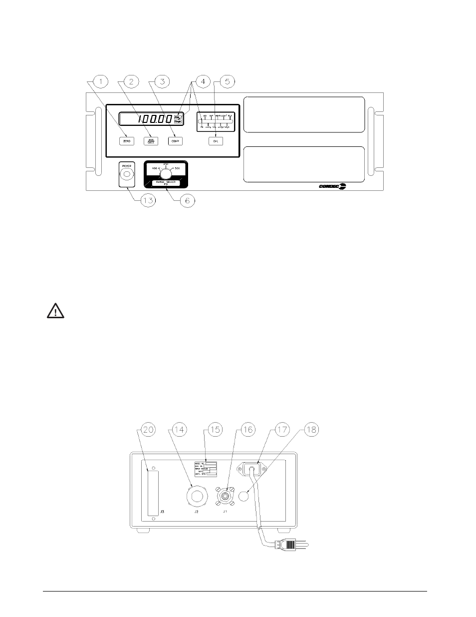
Figure 2-3. UPS3210 Rack-mountable Pressure Indicator Front Panel Functions
2.3
Rear Panel Configuration
UPS3000 Series, See Figure 2-4 below, contains the following:
1. AC power cord, and input receptacle (17).
2.
INPUT PRESSURE
port J1 (16), 7/16-20, 37
o
-4 AN male fitting.
Application of pressures greater than 1.5 times the highest pressure range of the indicator may cause
calibration errors or even permanent damage to the pressure transducer.
3. The unit’s identification plate (15).
4. Optional if required items:
•
Connector J2 (14), 5 pin round MS style connector, for Serial or Analog Output communication board.
•
Connector J3 (20), 15 pin D connector, for the PCM1000 Controller Interface.
•
Connector (18), 5 pin round connector, for the Freeze Mode Cable.
NOTE: For further information, see “Options, Replacement Kits” on page 54.
Figure 2-4. UPS3000 Desktop/Panel-mountable Pressure Indicator Rear View
#AUTION