STI AP-1-G-I User Manual
Page 9
- 17 -
Problem
Possible Cause
Possible Solution
9V DC battery clip not connected
Connect correctly
12-30V DC power source installation fault
Check installation
Master key switch not turned `ON'
Turn unit `ON' (vertical position)
Front cover fitted incorrectly
Check installation
Reversible mounting plate incorrectly installed
Check installation
Operating element depressed
Reset using reset key
Networked - The linked Alert Point is in `alarm'
condition
Reset the `networked' Alert Point
Tamper alarm activating
Check installation
Externally fitted detectors triggering Alert Point
Check linked units are not alarming
Networking DIL switch SW12 `ON' - but no
network required
DIL switch SW12 should be `OFF'
Connection lost between the `networked' Alert
Points
Check all wiring connections (including
COMMON)
5V6 zener diode not connected
Check detector terminals
Externally fitted detector connection broken
Check all wiring connections
9V DC battery output power insufficient
Low battery - change battery
DIL switch no. SW4 'ON' - the unit is expecting
external power, but not receiving any
Check ext power lead connections /
switch 'OFF' SW4 if no ext supply
Reset key not resetting Alert
Point when in `alarm' condition
Auto reset option turned `OFF'
DIL switch SW11 should be `ON'
No sound in `alarm' condition
Volume jumper connection loose or missing
Ensure the jumper connection is fitted
correctly
External sounder DIL switch SW6 turned `ON'
DIL switch SW6 should be `OFF'
External sounder connection fault
Check all wiring connections
External strobe/beacon DIL switch SW6 turned
`ON'
DIL switch SW6 should be `OFF'
External sounder connection fault
Check all wiring connections
No power
LED red & emitting a short beep
every 90 seconds
The Alert Point is constantly in
`alarm' condition
Tamper alarm sounding
External strobe / beacons not
flashing on activation
External sounders not alarming
on activation
LED red & emitting a short
double beep every 90 seconds
Troubleshooting
NEED TECHNICAL SUPPORT? FREEPHONE 0800 085 1678 (UK) TELEPHONE: +44 (0) 1527 520 999
General Maintenance:
9V DC batteries should be replaced every 15 months or sooner.
Cleaning should be carried out using only mild, diluted detergents: concentrated solutions and those
including (but not limited to) alkalis, strong acids, ethers, amines, aromatic hydrocarbons and
alcohols can cause considerable harm to this product.
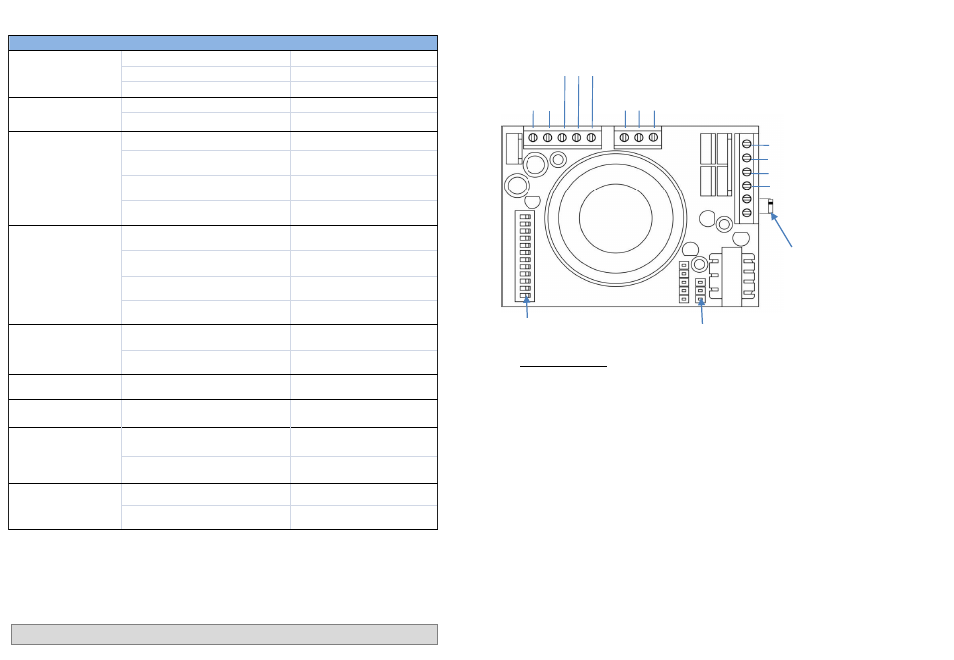
E
x
te
rn
a
l
P
o
w
e
r
+
E
x
te
rn
a
l
P
o
w
e
r
-
N
e
tw
o
rk
I
N
N
e
tw
o
rk
C
OM
N
e
tw
o
rk
OU
T
R
e
lay
N
.O.
R
e
lay
C
OM
R
e
lay
N
.C
.
External Sounder +
External Sounder -
External Strobe/Beacon +
External Strobe/Beacon -
External Detector +
External Detector -
PCB Terminal Diagram
Terminal connections
External power terminals
12-30V DC
Relay terminals
Max 30V DC, 1A
External sounder terminals
All external sounders need to be hard wired using 2 core
cable and must have their own power supply.
External strobes / beacons terminals
All external strobes & beacons need to be hard wired
and must have their own power supply.
Detector terminals
All detectors need to be hard wired on a N.O. loop, have
their own power supply and an end of line 5V6 Zener
diode fitted (supplied with the unit).
Using the relay terminals, wire the positive loop connection into the N.O. terminal and the negative loop
connection into the COM terminal.
The unit will independently sound during `alarm condition’ as well as sending a trigger signal back the
alarm panel.
It is recommended that all external detector wiring does not exceed 50 metres.
Volume jumper connection ( 3 pins )
DIL switch
Using the Alert Point as a Manual Call Point
- 18 -
5V6 Zener diode