Step 1. install the reversible mounting plate, Step 4. attach front cover – STI AP-1-G-I User Manual
Page 2
- 3 -
Specifications
Power source
9V DC battery (supplied) or 12-30V DC
Standby current
45µA
Alarm current
28mA low volume / 32mA high volume
Operating temperature
0ºC to 49ºC
Sounder output (at 1 metre)
95dB
– 102dB
Sounder tones
7
Tamper tone
1
Network
>2 Alert Points spaced less than 50m apart
Master Key
Switch Cylinder
Operating Element
1. Reversible Mounting Plate
Integral Sounder
9V DC Battery
Tamper Switch
3. Front Cover
Box Contents & Key Components
Contents
1.
Reversible Mounting Plate (x1)
2.
Chassis (x1)
3.
Front Cover (x1)
4.
Installation Kit (x1)
Reset Key
Master Key
4. Installation Kit
1” Screws (x4)
Rawlplugs (x4)
2. Chassis
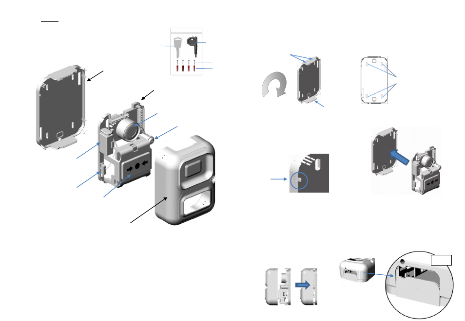
Alert Point Installation
Attach by pushing the chassis over the 4 fixing clips on the
mounting plate (highlighted ).
Fixing clip
- 4 -
Step 1. Install the Reversible Mounting Plate
Pilot point x2
Pilot point x1
The reversible mounting plate can be installed in
any orientation; depending on the required conduit
entry and exit points.
Mark the 4 fixing points (as shown) and install using
the screws and Rawlplugs provided.
Fixing Points x4
Step 2. Attaching the chassis
Step 3. Consult the User Manual for other programmable features
(Programmable Features page 8 & DIL switch settings page 19)
Step 4. Attach front cover
Line up each end using the channels located on the raised conduit sections (see detail). Push evenly
until the cover locks into place via 4 raised mounting clips situated on each corner.
Detail