Stuart Turner RG550-2 User Manual
Page 8
- 8 -
1
2
3
12
110
E
N
L
80
70
8
8
(Dims. in mm)
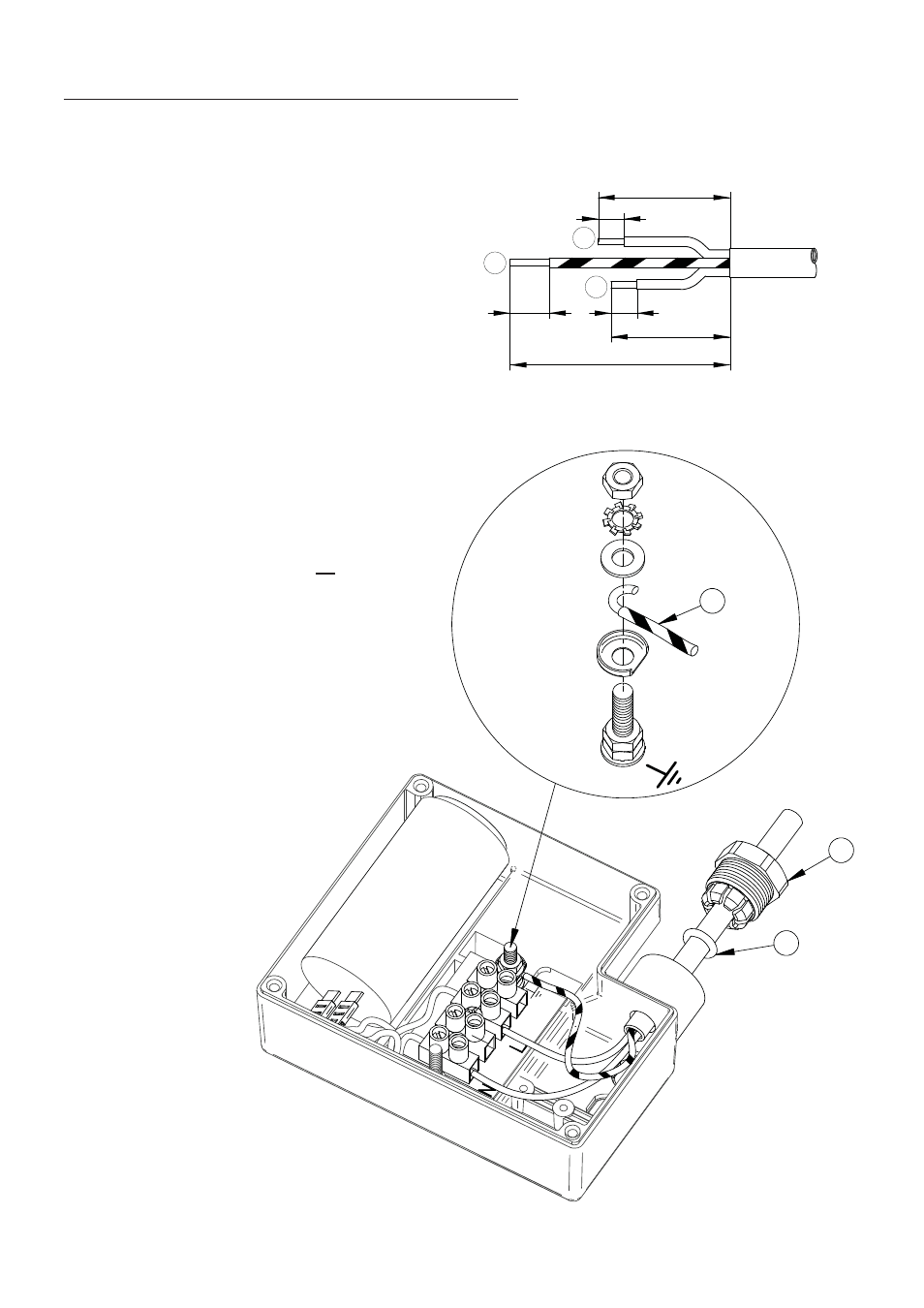
Fig. 3
Fig. 5
Fig. 4
Cable Gland & Supply Cord Fitting Instructions (Single phase range)
The cable gland assembly Fig. 5 (items 1 & 2) provides the necessary protection against
ingress of solid objects and moisture as well as providing cable retention.
Assembly instructions are as follows: -
1. Ensure selected cable sheath
diameter is within the permitted range
(6.5 to 9.5 mm).
2. Strip and prepare the cable sheath
and insulators as shown in Fig. 3.
3. Disassemble cable gland as shown in
Fig. 5 and insert cable into position
ensuring ‘O’-ring (item 1) is placed
over the cable before the clamping
insert (item 2) is tightened.
4. Consolidate the stranded conductor
ends by twisting and shape the earth conductor
as shown in Fig. 4 (item 3).
5. Remove earth terminal post clamping
components and assemble as shown in
Fig. 4 ensuring shaped conductor is
orientated as shown and all strands of
the conductor are clamped between
the
washers.
6. Insert and secure live and neutral
conductors ensuring all conductor
strands are clamped.
7. Confirm cable routing is as shown in
Fig. 5 and assemble and secure
terminal box lid.