Wiring diagram, Fuses – Stuart Turner Self Priming Jet 40 Centrifugal User Manual
Page 9
If the plug supplied is not suitable for your socket outlet, it should be cut off and
destroyed.
WARNING: A plug with bared flexible cords is hazardous if engaged in a
live socket outlet.
The end of the flexible cord should be suitably prepared and correct plug fitted, as
follows:
The wires in this mains lead (supply cord) are coloured in accordance with the following
code:
Green & Yellow: Earth
Blue:
Neutral
Brown: Live
As these colours may not correspond with the coloured markings identifying the
terminals in your plug, proceed as follows:
The wire which is coloured green and yellow must be connected to the terminal in the
plug which is marked with the letter 'E' or by the earth symbol or coloured green or
green and yellow.
The wire which is coloured Blue must be connected to the terminal which is marked
with the letter 'N' or coloured black or blue.
The wire which is coloured brown must be connected to the terminal which is marked
with the letter 'L' or coloured brown or red.
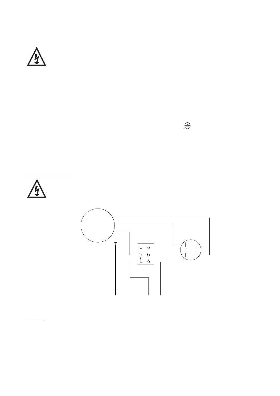
Wiring Diagram
The supply cord and internal wiring within the terminal box are routed
and secured to ensure compliance with the electrical standard EN 60335-1.
It is essential that any disturbance of this internal wiring is avoided and
the factory routing and securing of all internal wiring is always maintained.
- 9 -
Fuses
Important: The plug must be fitted with the following fuse size;
Jet 40: 13 Amp
Jet 90: 13 Amp
N
L
E
GR
EE
N/
YELLOW
BL
UE
BROWN
BLUE
MOTOR
6
3
N1
L4
L5
N2
BLACK
WHITE
RED
CAPACITOR
SWITCH
230 V, 1 phase supply
connected via a three
pin plug.
Fig. 8