Stuart Turner Self Priming Jet 40 Centrifugal User Manual
Page 7
- 7 -
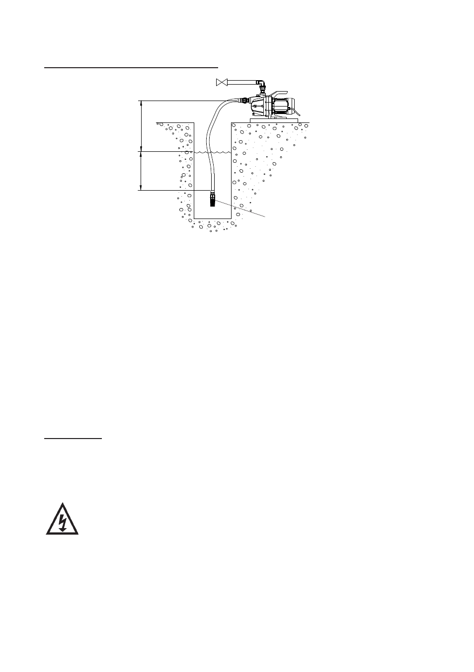
Pump Mounted Above Water Source (Suction Lift Installation)
The pumps can be used in a suction lift installation providing the height of lift is within
maximum permitted (Fig. 6).
It is important that the optional suction hose assembly is always used for suction lift
installations.
Lay the suction piping over the shortest possible distance and ensure there is a
constant rise from the water source to the pump. Any high spots will cause air pockets to
form reducing system efficiency.
Ensure all joints in suction pipework are completely airtight. Failure to comply will result
in loss of prime.
The intake of the footvalve/strainer should be positioned so that it cannot be blocked
with debris or silt that are frequently found in the bottom of sumps and wells.
When a footvalve is installed on installations that incorporate automatic pump control, it
is recommended that a suitable pressure relief valve be fitted in the discharge (outlet)
pipework from the pump.
Self Priming
Jet 40 and 90 pumps are capable of self priming the suction hose assembly provided
the optional suction hose is always used for this type of installation.
ELECTRICAL INSTALLATION
WARNINGS:
•
The electrical installation must be carried out in accordance with the
current national electrical regulations and installed by a competent
person.
•
In the interests of electrical safety a 30 mA. residual current device
(R.C.D.) should be installed in the supply circuit. This may be part of
a consumer unit or a separate unit.
•
Before starting work on the electrical installation ensure the power
supply is isolated.
•
This appliance must be earthed.
•
The motor and wiring must not be exposed to water.
Diagram showing typical suction lift installation.
Fig. 6
Max. suction
lift
7
m
Ensure inlet area around inlet
strainer is free from debris
0.5
m min