Installation – Sterling QVEF User Manual
Page 6
6
INSTALLATION
(continued)
Unit heaters should not be installed to maintain low
temperatures and/or freeze protection of buildings.
A minimum of 50°F (10°C) thermostat setting must
be maintained. If unit heaters are operated to maintain
lower than 50°F (10°C), hot fl ue gases are cooled inside
the heat exchanger to a point where water vapor (a fl ue
gas by- product) condenses onto the heat exchanger
walls. The result is a mildly corrosive acid that prematurely
corrodes the aluminized heat exchanger and can actually
drip water down from the unit heater onto fl oor surface.
Additional unit heaters should be installed if a minimum
50°F (10°C) thermostat setting cannot be maintained.
AIR FOR COMBUSTION:The Unit Heater shall be
installed in a location in which the facilities for
ventilation permit satisfactory combustion of gas,
proper venting, and the maintenance of ambient
temperature at safe limits under normal conditions of
use. The Unit Heater shall be located in such a manner
as not to interfere with proper circulation of air within the
confi ned space. When buildings are so tight that normal
infi ltration does not meet air requirements, outside air
shall be introduced per Sections 1.3.4.2 and 1.3.4.3 of
ANSI Z223.1 for combustion requirements. A permanent
opening or openings having a total free area of not less
than one square inch per 5,000 BTU/HR. (1.5 Kw) of
total input rating of all appliances within the space shall
be provided.
NOTICE: Unit heater sizing should be based on heat
loss calculations where the unit heater output equals
or exceeds heat loss. Heater output is approximately
80% of input BTU/HR. rating.
CLEARANCES: Each Gas Unit Heater shall be located
with respect to building construction and other equipment
so as to permit access to the Unit Heater. Clearance
between walls and the vertical sides of the Unit Heater
shall be no less than 18 inches (457mm). A minimum
clearance of 6 inches (152mm) must be maintained
between the top of the Unit Heater and the ceiling. The
bottom of the Unit Heater must be no less than 12 inches
(305 mm) from any combustible. However, in order to
ensure access to the burner compartment, a minimum
distance of 21 inches (533 mm) is required. The distance
between the flue collector and any combustible must
be no less than 6 inches (152mm). Also see AIR FOR
COMBUSTION and VENTING sections.
NOTICE: Increasing the clearance distances may
be necessary if there is a possibility of distortion or
discoloration of adjacent materials.
Make certain that the lifting
methods used to lift the heater and the method
of suspension used in the fi eld installation of the
heater are capable of uniformly supporting the
weight of the heater at all times. Failure to heed
this warning may result in property damage or
personal injury!
Make certain that the structure
to which the heater is mounted is capable of
supporting its weight. Under no circumstances
must the gas lines, the venting system or the
electrical conduit be used to support the heater;
or should any other objects (i.e. ladder, person)
lean against the heater, gas lines, venting system
or the electrical conduit for support.
Unit heaters must be hung level
from side to side and from front to back, see
Figures 1 through 4. Failure to do so will result
in poor performance and or premature failure of
the unit.
Insure that all hardware used in
the suspension of each unit heater is more than
adequate for the job. Failure to do so may result
in extensive property damage, severe personal
injury or death.
personal injury or death!
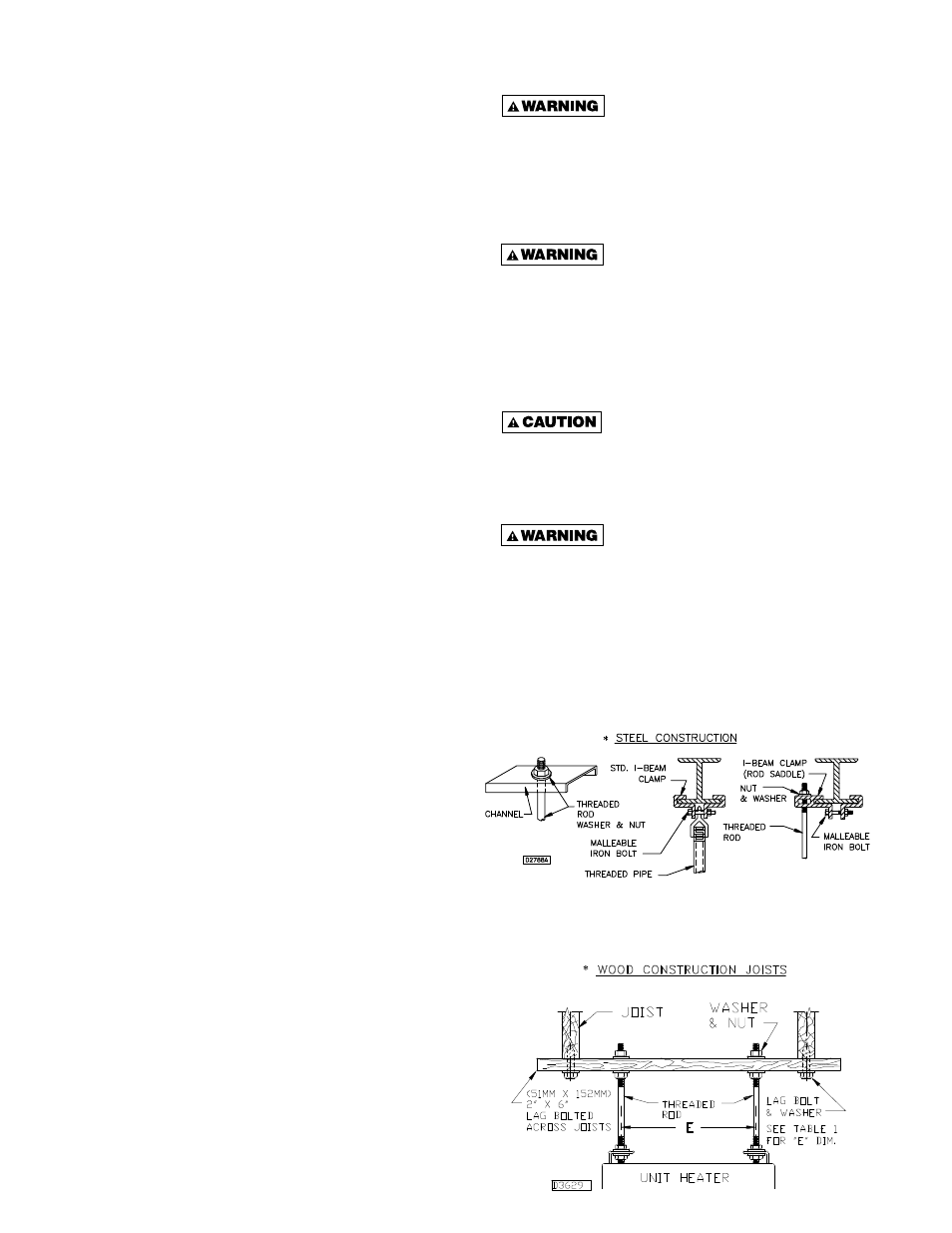
Refer to Figures 1 through 4, and dimensional data
per Table 1 for suspension of units.
Figure 3A - Heater Mounting*
*All hanging hardware and wood is not included with the unit
(To be fi eld supplied).
Figure 3B - Heater Mounting 100/400 MBTU Unit Sizes