Venting – Sterling QVEF User Manual
Page 11
11
Use single wall pipe constructed of 26 gauge galvanized
steel or material of equivalent durability and corrosion
resistance for the vent system. For installation in Canada,
use pipe constructed from 0.025 inch thick aluminum or
0.018 inch thick stainless steel.
Never use a pipe of a diameter
other than that specified in Table 1! Never use
PVC or other nonmetallic pipe for venting! To do
so may result in serious damage to the unit or
severe personal injury or death!
Any run of single wall vent pipe passing through an
unheated space must be insulated with and insulation
suitable to 550°F.
The vent terminal must be installed with a minimum
clearance of four feet (1.2m) from electric meters, gas
meters, regulators and relief equipment.
Seal ALL vent pipe joints and seams to prevent leakage.
Use General Electric RTV-108 or DowCorning RTV-732
silicone sealant (or equivalent); or 3M #425 aluminum
foil tape (or equivalent).
The vent system must be installed to prevent collection
of condensate. Vertical vent pipes should be equipped
with condensate drains. Pitch horizontal pipes downward
1/4 in. per foot (21mm per meter) toward outlet for
condensate drainage.
Horizontal por tions of the venting system shall be
supported at maximum intervals of four feet (1.2m)
to prevent sagging (in Canada, support at 3 feet (1m)
minimum intervals).
Insulate single wall vent pipe exposed to cold air or
running through unheated areas.
Each unit must have an individual vent pipe and
vent terminal per furnace section! Each unit MUST
NOT be connected to other vent systems or to a
chimney.
Horizontal Venting: Units are shipped from the factory
set up for vertical venting. To convert the power venter
for horizontal venting, remove the shipping support
bracket; refer to Figures 6 through 10 and 17, and
follow this procedure:
1. Hold power venter motor in position.
2. Remove the three Phillips-head screws from the
motor adaptor plate.
3. Remove the three screws which connect the
power venter stack to the power venter housing.
4. Rotate the power venter housing to the horizontal
position.
5. Replace screws accordingly.
NOTICE: The motor, pressure switch, and junction
box bracket MUST remain located as shipped from
the factory. Rotate only the blower housing! If the
power venter housing is to be moved to the right
horizontal position, the junction box must be rotated
90 degrees CCW to clear the connection. To do this,
remove all wires, conduit and conduit connector
from the junction box, noting location of wires. Move
box, using holes provided. Move 7/8" plug from
bottom of box to side. Reconnect all wires according
to the unit's wiring diagram.
VENTING
(continued)
REFER TO SPECIFICATION TABLE AND INSTALLATION MANUAL FOR PROPER USAGE
The following instructions apply to Canadian installations in addition to installation and operating instructions:
1. Installation must conform with local building codes, or in absence of local codes, with current CSA-B149.1 Installation Codes for Natural
Gas Burning Appliances and Equipment, or CSA-B149.2, Installation Codes for Propane Gas Burning Appliances and Equipment.
2. Any references to U.S. standards or codes in these instructions are to be ignored and the applicable Canadian standards or codes applied.
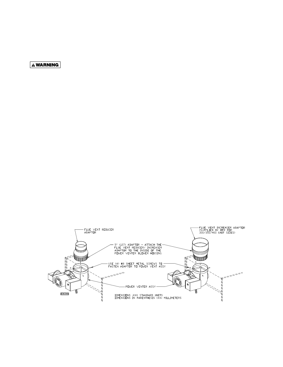
3. The reducer must be fi eld supplied for 100, 125, 150 and 175 MBH unit sizes.
4. If using a metal vent system under positive gauge pressure in Canada, a slip fi t vent connection must be secured by at least two corrosion-
resistant screws, or other mechanical locking means.
5. The vent shall not terminate – (a) Less than 6 ft. (1.8m) from a combustion air inlet of another appliance. (b) Less than 3 ft. (1m) from any
other building opening or any gas service regulator. (c) Directly above a gas utility meter or service regulator.
Figure 9
Adaptor
Installation