Sterling HS User Manual
Page 2
2
TABLE OF CONTENTS
GENERAL SAFETY INFORMATION .......................... 3
SPECIFICATIONS
Dimensional Data .................................................. 4
Steam Performance Data ....................................... 5
Steam Calculations & Correction Factors ............... 6
Hot Water Performance Data ................................. 7
Hot Water Calculations & Correction Factors ........ 8
Technical Data ....................................................... 9
Motor Data ........................................................... 10
LOCATION ................................................................ 11
INSTALLATION
Unit
Mounting
....................................................... 12
Piping
...............................................................12-16
The following terms are used throughout this manual, in addition to ETL requirements, to bring attention to the
presence of potential hazards or to important information concerning the product:
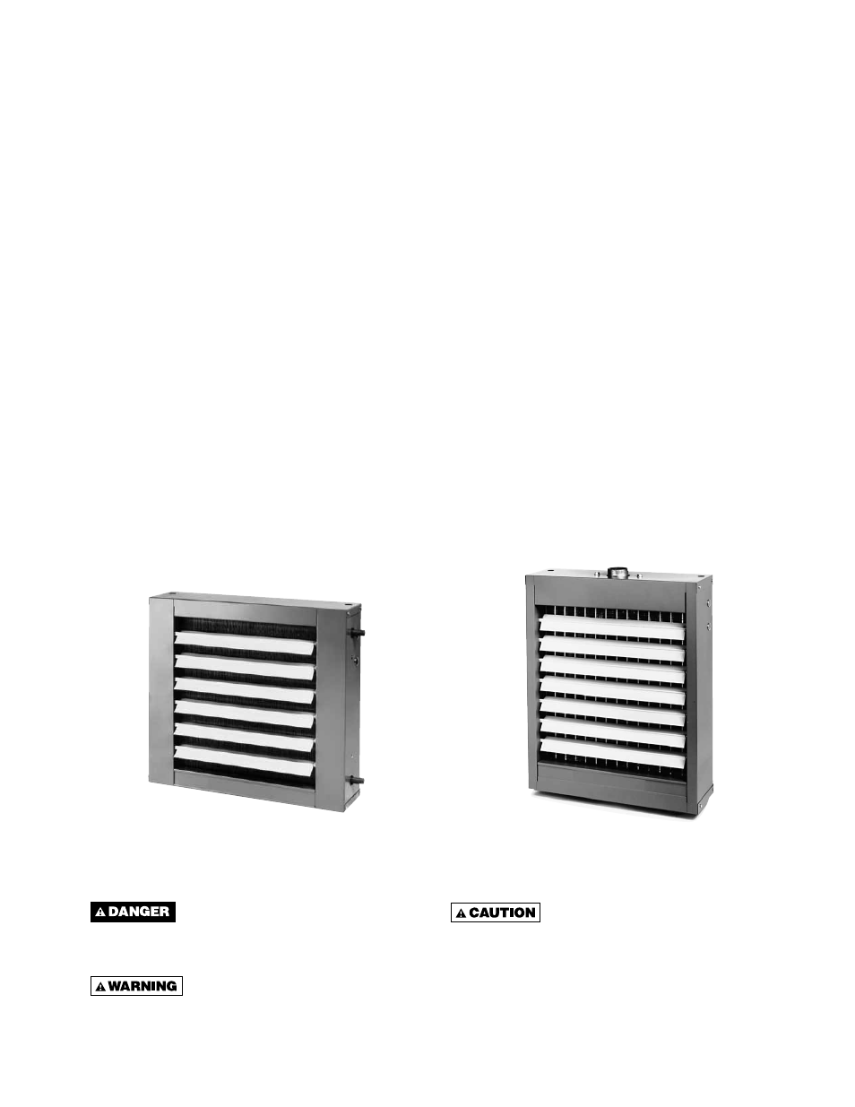
Horizontal hydronic unit heaters are available in both
serpentine and header type units. Serpentine units offer
outputs from 8,030 to 35,900 BTU’s (2.4 to 10.5 kW) and
are ideal for hot water (only) installations with limited
clearances. Header type horizontal units range from
18,000 to 360,000 (5.3 to 105.5 kW) and can operate
with either hot water or steam. Both units are furnished
Figure 1
Serpentine
Type
Indicates an imminently hazardous
situation which, if not avoided, will result in death,
serious injury or substantial property damage.
Indicates an imminently hazardous
situation which, if not avoided, could result in
death, serious injury or substantial property
damage.
Indicates an imminently hazardous
situation which, if not avoided, may result in minor
injury or property damage.
NOTICE: Used to notify of special instructions on
installation, operation or maintenance which are
important to equipment but not related to personal
injury hazards.
ELECTRICAL CONNECTIONS ................................ 17
Operation
............................................................. 17
Thermostat Wiring and Location .......................... 17
WIRING INSTALLATION .......................................... 18
OPTIONS ................................................................. 19
MAINTENANCE ....................................................... 20
REPLACEMENT PARTS .......................................... 21
TROUBLESHOOTING GUIDE .................................. 22
WARRANTY .............................................................. 23
INSPECTION SHEET ................................................ 24
NOTICE: It is the owner’s responsibility to provide any scaffolding or other apparatus required to perform
emergency service or annual/periodic maintenance to this equipment.
Figure 2
Header
Type
with totally enclosed motors, with explosion proof motors
as optional on header types. The designs are certifi ed
by ETL. Do not alter these units in any way and do
not attach any ductwork to the units. If you have
any questions after reading this manual, contact the
manufacturer.
DESCRIPTION